Page 165 - Shigley's Mechanical Engineering Design
P. 165

bud29281_ch03_071-146.qxd  11/30/2009  5:50 pm  Page 140 pinnacle 203:MHDQ196:bud29281:0073529281:bud29281_pagefiles:


                 140   Mechanical Engineering Design
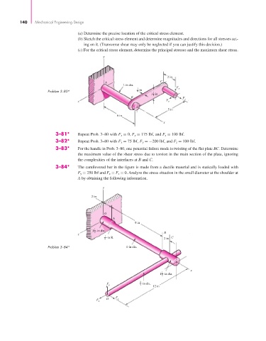
                                          (a) Determine the precise location of the critical stress element.
                                          (b) Sketch the critical stress element and determine magnitudes and directions for all stresses act-
                                             ing on it. (Transverse shear may only be neglected if you can justify this decision.)
                                          (c) For the critical stress element, determine the principal stresses and the maximum shear stress.
                                                     y


                                                                                 2 in
                                                      A                       C
                                                              1-in dia.
                                                                                     F
                                                                    1  in             y
                             Problem 3–80*                          4      1
                                                                          1 in
                                                                           2
                                                                 B                      F
                                          z                                     F z     x
                                                                                 5 in
                                                           6 in
                                                                               x

                                3–81*     Repeat Prob. 3–80 with F x = 0, F y = 175 lbf, and F z = 100 lbf.
                                3–82*     Repeat Prob. 3–80 with F x = 75 lbf, F y =−200 lbf, and F z = 100 lbf.
                                3–83*     For the handle in Prob. 3–80, one potential failure mode is twisting of the flat plate BC. Determine
                                          the maximum value of the shear stress due to torsion in the main section of the plate, ignoring
                                          the complexities of the interfaces at B and C.
                                3–84*     The cantilevered bar in the figure is made from a ductile material and is statically loaded with
                                          F y = 250 lbf and F x = F z = 0. Analyze the stress situation in the small diameter at the shoulder at
                                          A by obtaining the following information.
                                                     y

                                                2 in


                                                     O
                                                         A
                                                                   9 in
                                                 1
                                                1 -in dia.
                                                 2                             B
                                          z
                                                      1 -in R.                     C
                                                      8                        2 in
                             Problem 3–84*                     1-in dia.


                                                                                           x
                                                                              1
                                                                              1 -in dia.
                                                                              2
                                                                     3
                                                                       n
                                                                      i

                                                                        i
                                                                        d
                                                       F              - -in dia. a .
                                                                     4
                                                       y
                                                                           12 in
                                                  F z  D  F x
   160   161   162   163   164   165   166   167   168   169   170