Page 164 - Shigley's Mechanical Engineering Design
P. 164

bud29281_ch03_071-146.qxd  11/25/09  4:55PM  Page 139 ntt 203:MHDQ196:bud29281:0073529281:bud29281_pagefiles:


                                                                                             Load and Stress Analysis  139
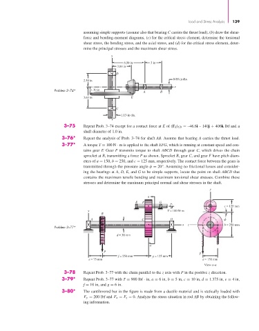
                                               assuming simple supports (assume also that bearing C carries the thrust load), (b) draw the shear-
                                               force and bending-moment diagrams, (c) for the critical stress element, determine the torsional
                                               shear stress, the bending stress, and the axial stress, and (d) for the critical stress element, deter-
                                               mine the principal stresses and the maximum shear stress.
                                                           y
                                                                 6.50 in     3 in
                                                              3.88 in
                                                             D
                                                                                       0.88-in dia.
                                               2.50 in
                                                                                       x
                                  Problem 3–74*   1.30 in                 A      B
                                               3.63 in              E

                                                             C
                                                                1.13-in dia.
                                      3–75     Repeat Prob. 3–74 except for a contact force at E of (F E ) CD = –46.6i – 140j + 406k lbf and a
                                               shaft diameter of 1.0 in.
                                     3–76*     Repeat the analysis of Prob. 3–74 for shaft AB. Assume that bearing A carries the thrust load.
                                     3–77*     A torque T = 100 N · m is applied to the shaft EFG, which is running at constant speed and con-
                                               tains gear F. Gear F transmits torque to shaft ABCD through gear C, which drives the chain
                                               sprocket at B, transmitting a force P as shown. Sprocket B, gear C, and gear F have pitch diam-
                                               eters of a = 150, b = 250, and c = 125 mm, respectively. The contact force between the gears is
                                               transmitted through the pressure angle φ = 20°. Assuming no frictional losses and consider-
                                               ing the bearings at A, D, E, and G to be simple supports, locate the point on shaft ABCD that
                                               contains the maximum tensile bending and maximum torsional shear stresses. Combine these
                                               stresses and determine the maximum principal normal and shear stresses in the shaft.
                                                                                                       y
                                                                           a
                                                                      E  F       G
                                                                                                              c = 125 mm
                                                 y                                  T = 100 N m       T
                                                       B
                                                  A                      C            D
                                                                                           x  z              b = 250 mm
                                  Problem 3–77*
                                                              d = 30 mm

                                                                            a
                                                        P
                                                                                                  P
                                                              f = 250 mm     g = 125 mm
                                                 e = 75 mm                                          a = 150 mm
                                                                                                     View a–a
                                      3–78     Repeat Prob. 3–77 with the chain parallel to the z axis with P in the positive z direction.
                                     3–79*     Repeat Prob. 3–77 with T = 900 lbf · in, a = 6 in, b = 5 in, c = 10 in, d = 1.375 in, e = 4 in,
                                               f = 10 in, and g = 6 in.
                                     3–80*     The cantilevered bar in the figure is made from a ductile material and is statically loaded with
                                               F y = 200 lbf and F x = F z = 0. Analyze the stress situation in rod AB by obtaining the follow-
                                               ing information.
   159   160   161   162   163   164   165   166   167   168   169