Page 159 - Shigley's Mechanical Engineering Design
P. 159

bud29281_ch03_071-146.qxd  11/25/09  4:55PM  Page 134 ntt 203:MHDQ196:bud29281:0073529281:bud29281_pagefiles:


                 134   Mechanical Engineering Design

                                          significance of the transverse shear stress in combination with bending by performing the
                                          following steps.
                                          (a) Assume L = 10 in. For points A, B, and C, sketch three-dimensional stress elements, labeling
                                             the coordinate directions and showing all stresses. Calculate magnitudes of the stresses on the
                                             stress elements. Do not neglect transverse shear stress. Calculate the maximum shear stress
                                             for each stress element.
                                          (b) For each stress element in part (a), calculate the maximum shear stress if the transverse shear
                                             stress is neglected. Determine the percent error for each stress element from neglecting the
                                             transverse shear stress.
                                          (c) Repeat the problem for L = 4, 1, and 0.1 in. Compare the results and state any conclusions
                                            regarding the significance of the transverse shear stress in combination with bending.
                                 3–46     Consider a simply supported beam of rectangular cross section of constant width b and variable
                                          depth h, so proportioned that the maximum stress σ x at the outer surface due to bending is con-
                                          stant, when subjected to a load F at a distance a from the left support and a distance c from the
                                          right support. Show that the depth h at location x is given by

                                                                        6Fcx
                                                                  h =           0 ≤ x ≤ a
                                                                        lbσ max
                                 3–47     In Prob. 3–46, h → 0 as x → 0, which cannot occur. If the maximum shear stress τ max due to
                                          direct shear is to be constant in this region, show that the depth h at location x is given by

                                                                   3  Fc            3 Fcσ max
                                                               h =           0 ≤ x ≤    2
                                                                   2 lbτ max        8 lbτ
                                                                                        max
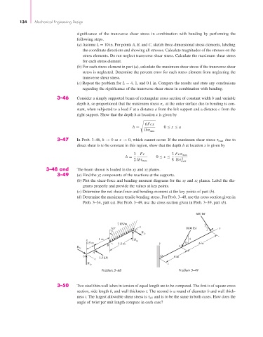
                            3–48 and      The beam shown is loaded in the xy and xz planes.
                                 3–49     (a) Find the yz components of the reactions at the supports.
                                          (b) Plot the shear-force and bending-moment diagrams for the xy and xz planes. Label the dia-
                                             grams properly and provide the values at key points.
                                          (c) Determine the net shear-force and bending-moment at the key points of part (b).
                                          (d) Determine the maximum tensile bending stress. For Prob. 3–48, use the cross section given in
                                             Prob. 3–34, part (a). For Prob. 3–49, use the cross section given in Prob. 3–39, part (b).

                                                                                              600 lbf

                                                            2 kN/m                                1
                                                                     x
                                                         30°                              1000 lbf   B  x
                                                                    C                              1
                                                                      R 2z
                                              y    1 m             R 2y                    4
                                              0.5 m         1.5 m             y          3      6 in
                                          R            B                               A
                                           1z
                                                 A
                                             O                                 O     4 in
                                                  z  1.5 kN
                                               R 1y                               z
                                                     Problem 3–48                      Problem 3–49

                                 3–50     Two steel thin-wall tubes in torsion of equal length are to be compared. The first is of square cross
                                          section, side length b, and wall thickness t. The second is a round of diameter b and wall thick-
                                          ness t. The largest allowable shear stress is τ all and is to be the same in both cases. How does the
                                          angle of twist per unit length compare in each case?
   154   155   156   157   158   159   160   161   162   163   164