
Page 158 - Shigley's Mechanical Engineering Design
P. 158
bud29281_ch03_071-146.qxd 11/25/09 4:55PM Page 133 ntt 203:MHDQ196:bud29281:0073529281:bud29281_pagefiles:
Load and Stress Analysis 133
shown in part c of the figure to determine a minimum pin diameter for each of the following
potential failure modes.
(a) Consider failure based on bending at the point of maximum bending stress in the pin.
(b) Consider failure based on the average shear stress on the pin cross section at the interface
plane of the knuckle and clevis.
(c) Consider failure based on shear at the point of the maximum transverse shear stress in the pin.
3–43 The figure illustrates a pin tightly fitted into a hole of a substantial member. A usual analysis
is one that assumes concentrated reactions R and M at distance l from F. Suppose the reaction
is distributed linearly along distance a. Is the resulting moment reaction larger or smaller than
the concentrated reaction? What is the loading intensity q? What do you think of using the
usual assumption?
F
l a
Problem 3–43
3–44 For the beam shown, determine (a) the maximum tensile and compressive bending stresses,
(b) the maximum shear stress due to V, and (c) the maximum shear stress in the beam.
1800 lbf 1 in
300 lbf/in
A B C
3 in
Problem 3–44
1 in
10 in 30 in
3 in
Cross section (enlarged)
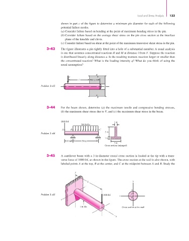
3–45 A cantilever beam with a 1-in-diameter round cross section is loaded at the tip with a trans-
verse force of 1000 lbf, as shown in the figure. The cross section at the wall is also shown, with
labeled points A at the top, B at the center, and C at the midpoint between A and B. Study the
y
y
L
A
Problem 3–45 1000 lbf C
z
B
z
1 in dia. Cross section at the wall
x