Page 235 - Shigley's Mechanical Engineering Design
P. 235

bud29281_ch04_147-211.qxd  11/30/2009  8:50 pm  Page 210 pinnacle 203:MHDQ196:bud29281:0073529281:bud29281_pagefiles:


                 210    Mechanical Engineering Design
                                4–110     If drawn, a figure for this problem would resemble that for Prob. 4–90. A strut that is a standard
                                                                                                        1
                                          hollow right circular cylinder has an outside diameter of 3 in and a wall thickness of  in and is
                                                                                                        4
                                          compressed between two circular end plates held by four bolts equally spaced on a bolt circle
                                          of 4.5-in diameter. All four bolts are hand-tightened, and then bolt A is tightened to a tension
                                          of 1500 lbf and bolt C, diagonally opposite, is tightened to a tension of 9000 lbf. The strut
                                          axis of symmetry is coincident with the center of the bolt circles. Find the maximum compres-
                                          sive load, the eccentricity of loading, and the largest compressive stress in the strut.
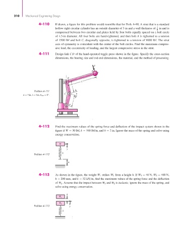
                                4–111     Design link CD of the hand-operated toggle press shown in the figure. Specify the cross-section
                                          dimensions, the bearing size and rod-end dimensions, the material, and the method of processing.

                                                                  F
                                                                A

                                                 B
                                                          L
                                                    l
                             Problem 4–111
                                               C
                      L = 9 in, l = 3 in, θ min = 0°.
                                                     l
                                                  D


                                4–112     Find the maximum values of the spring force and deflection of the impact system shown in the
                                          figure if W = 30 lbf, k = 100 lbf/in, and h = 2 in. Ignore the mass of the spring and solve using
                                          energy conservation.


                                            W
                                                 y
                                              k
                             Problem 4–112
                                                  h


                                4–113     As shown in the figure, the weight W 1 strikes W 2 from a height h. If W 1 = 40 N, W 2 = 400 N,
                                          h = 200 mm, and k = 32 kN/m, find the maximum values of the spring force and the deflection
                                          of W 2 . Assume that the impact between W 1 and W 2 is inelastic, ignore the mass of the spring, and
                                          solve using energy conservation.

                                                 h
                                            W 1
                                            W 2
                             Problem 4–113         y
                                               k
   230   231   232   233   234   235   236   237   238   239   240