
Page 232 - Shigley's Mechanical Engineering Design
P. 232
bud29281_ch04_147-211.qxd 11/27/09 2:55PM Page 207 ntt 203:MHDQ196:bud29281:0073529281:bud29281_pagefiles:
Deflection and Stiffness 207
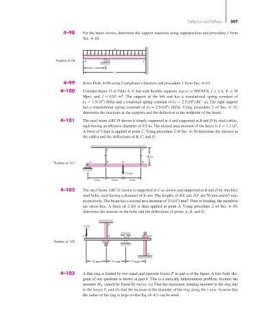
4–98 For the beam shown, determine the support reactions using superposition and procedure 1 from
Sec. 4–10.
w
Problem 4–98 A B C
a
l
4–99 Solve Prob. 4–98 using Castigliano’s theorem and procedure 1 from Sec. 4–10.
4–100 Consider beam 13 in Table A–9, but with flexible supports. Let w = 500 lbf/ft, l = 2 ft, E = 30
4
Mpsi, and I = 0.85 in . The support at the left end has a translational spring constant of
6
6
k 1 = 1.5(10 ) lbf/in and a rotational spring constant of k 2 = 2.5(10 ) lbf in. The right support
6
has a translational spring constant of k 3 = 2.0 (10 ) lbf/in. Using procedure 2 of Sec. 4–10,
determine the reactions at the supports and the deflection at the midpoint of the beam.
4–101 The steel beam ABC D shown is simply supported at A and supported at B and D by steel cables,
4
each having an effective diameter of 0.5 in. The second area moment of the beam is I = 1.2 in .
A force of 5 kips is applied at point C. Using procedure 2 of Sec. 4–10 determine the stresses in
the cables and the deflections of B, C, and D.
E F
38 in
Problem 4–101 A B C D
5 kips
16 in 16 in 16 in
4–102 The steel beam ABC D shown is supported at C as shown and supported at B and D by shoulder
steel bolts, each having a diameter of 8 mm. The lengths of BE and DF are 50 mm and 65 mm,
4
3
respectively. The beam has a second area moment of 21(10 ) mm . Prior to loading, the members
are stress-free. A force of 2 kN is then applied at point A. Using procedure 2 of Sec. 4–10,
determine the stresses in the bolts and the deflections of points A, B, and D.
E
2 kN
A B C D
Problem 4–102
F
75 mm 75 mm 75 mm
4–103 A thin ring is loaded by two equal and opposite forces F in part a of the figure. A free-body dia-
gram of one quadrant is shown in part b. This is a statically indeterminate problem, because the
moment M A cannot be found by statics. (a) Find the maximum bending moment in the ring due
to the forces F, and (b) find the increase in the diameter of the ring along the y axis. Assume that
the radius of the ring is large so that Eq. (4–41) can be used.