
Page 233 - Shigley's Mechanical Engineering Design
P. 233
bud29281_ch04_147-211.qxd 11/27/09 2:55PM Page 208 ntt 203:MHDQ196:bud29281:0073529281:bud29281_pagefiles:
208 Mechanical Engineering Design
y
y
F
B B
ds
d
R
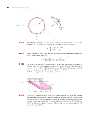
Problem 4–103 A A
x x
C O O
M A
F
2
D
F
(a) (b)
4–104 A round tubular column has outside and inside diameters of D and d, respectively, and a diame-
tral ratio of K = d/D. Show that buckling will occur when the outside diameter is
1/4
2
64P cr l
D =
4
3
π CE(1 − K )
4–105 For the conditions of Prob. 4–104, show that buckling according to the parabolic formula will
occur when the outside diameter is
1/2
2
P cr S y l
D = 2 +
2
2
2
πS y (1 − K ) π CE(1 + K )
4–106 Link 2, shown in the figure, is 25 mm wide, has 12-mm-diameter bearings at the ends, and is cut
from low-carbon steel bar stock having a minimum yield strength of 165 MPa. The end-condition
constants are C = 1 and C = 1.2 for buckling in and out of the plane of the drawing, respectively.
(a) Using a design factor n d = 4, find a suitable thickness for the link.
(b) Are the bearing stresses at O and B of any significance?
y
1
x
Problem 4–106 2 A
O 3
500 mm 800 N
B C
900 mm 750 mm
4–107 Link 3, shown schematically in the figure, acts as a brace to support the 270-lbf load. For buck-
ling in the plane of the figure, the link may be regarded as pinned at both ends. For out-of-plane
buckling, the ends are fixed. Select a suitable material and a method of manufacture, such as forg-
ing, casting, stamping, or machining, for casual applications of the brace in oil-field machinery.
Specify the dimensions of the cross section as well as the ends so as to obtain a strong, safe, well-
made, and economical brace.