
Page 234 - Shigley's Mechanical Engineering Design
P. 234
bud29281_ch04_147-211.qxd 11/30/2009 4:12 pm Page 209 pinnacle s-171:Desktop Folder:Temp Work:Don't Delete (Jobs):MHDQ196/Budynas:
Deflection and Stiffness 209
y
B
F = 270 1bf
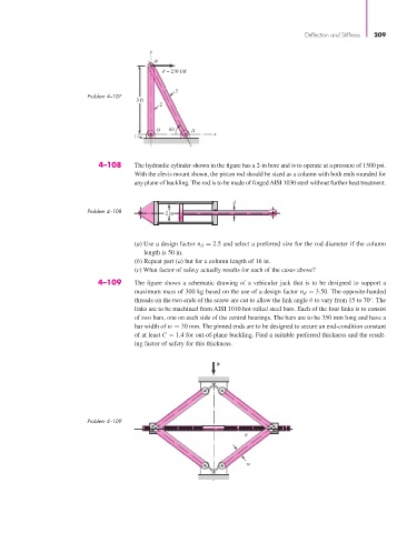
3
Problem 4–107
3 ft
2
O 60 A
x
1
4–108 The hydraulic cylinder shown in the figure has a 2-in bore and is to operate at a pressure of 1500 psi.
With the clevis mount shown, the piston rod should be sized as a column with both ends rounded for
any plane of buckling. The rod is to be made of forged AISI 1030 steel without further heat treatment.
d
Problem 4–108 2 in
(a) Use a design factor n d = 2.5 and select a preferred size for the rod diameter if the column
length is 50 in.
(b) Repeat part (a) but for a column length of 16 in.
(c) What factor of safety actually results for each of the cases above?
4–109 The figure shows a schematic drawing of a vehicular jack that is to be designed to support a
maximum mass of 300 kg based on the use of a design factor n d = 3.50. The opposite-handed
threads on the two ends of the screw are cut to allow the link angle θ to vary from 15 to 70 . The
◦
links are to be machined from AISI 1010 hot-rolled steel bars. Each of the four links is to consist
of two bars, one on each side of the central bearings. The bars are to be 350 mm long and have a
bar width of w = 30 mm. The pinned ends are to be designed to secure an end-condition constant
of at least C = 1.4 for out-of-plane buckling. Find a suitable preferred thickness and the result-
ing factor of safety for this thickness.
W
Problem 4–109
w