
Page 239 - Shigley's Mechanical Engineering Design
P. 239
bud29281_ch05_212-264.qxd 11/27/2009 6:46 pm Page 214 pinnacle s-171:Desktop Folder:Temp Work:Don't Delete (Jobs):MHDQ196/Budynas:
214 Mechanical Engineering Design
In Chap. 1 we learned that strength is a property or characteristic of a mechanical
element. This property results from the material identity, the treatment and processing
incidental to creating its geometry, and the loading, and it is at the controlling or critical
location.
In addition to considering the strength of a single part, we must be cognizant
that the strengths of the mass-produced parts will all be somewhat different from the
others in the collection or ensemble because of variations in dimensions, machining,
forming, and composition. Descriptors of strength are necessarily statistical in
nature, involving parameters such as mean, standard deviations, and distributional
identification.
A static load is a stationary force or couple applied to a member. To be stationary,
the force or couple must be unchanging in magnitude, point or points of application,
and direction. A static load can produce axial tension or compression, a shear load, a
bending load, a torsional load, or any combination of these. To be considered static, the
load cannot change in any manner.
In this chapter we consider the relations between strength and static loading in order
to make the decisions concerning material and its treatment, fabrication, and geometry
for satisfying the requirements of functionality, safety, reliability, competitiveness,
usability, manufacturability, and marketability. How far we go down this list is related
to the scope of the examples.
“Failure” is the first word in the chapter title. Failure can mean a part has sepa-
rated into two or more pieces; has become permanently distorted, thus ruining its
geometry; has had its reliability downgraded; or has had its function compromised,
whatever the reason. A designer speaking of failure can mean any or all of these pos-
sibilities. In this chapter our attention is focused on the predictability of permanent
distortion or separation. In strength-sensitive situations the designer must separate
mean stress and mean strength at the critical location sufficiently to accomplish his
or her purposes.
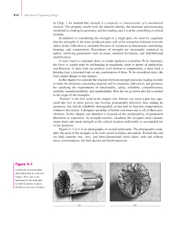
Figures 5–1 to 5–5 are photographs of several failed parts. The photographs exem-
plify the need of the designer to be well-versed in failure prevention. Toward this end
we shall consider one-, two-, and three-dimensional stress states, with and without
stress concentrations, for both ductile and brittle materials.
Figure 5–1
(a) Failure of a truck drive-
shaft spline due to corrosion
fatigue. Note that it was
necessary to use clear tape
to hold the pieces in place.
(b) Direct end view of failure.