Page 252 - Shigley's Mechanical Engineering Design
P. 252

bud29281_ch05_212-264.qxd  11/27/2009  6:46 pm  Page 227 pinnacle s-171:Desktop Folder:Temp Work:Don't Delete (Jobs):MHDQ196/Budynas:


                                                                                     Failures Resulting from Static Loading  227

                                               MSS From Eq. (3–16),
                                                                      σ 1 − σ 3  0 − (−68.0)
                                                                τ max =      =            = 34.0 kpsi
                                                                        2           2
                                                                          S y /2  100/2
                                     Answer                           n =      =       = 1.47
                                                                          τ max   34.0
                                               (e) The ordered principal stresses are σ 1 = 30,σ 2 = 30,σ 3 = 30 kpsi
                                               DE  From Eq. (5–12),

                                                               (30 − 30) + (30 − 30) + (30 − 30)
                                                                       2          2          2    1/2

                                                         σ =                                      = 0 kpsi
                                                                              2
                                     Answer                              n =  S y  =  100  →∞
                                                                             σ     0

                                               MSS From Eq. (5–3),

                                     Answer                          n =   S y  =   100  →∞
                                                                         σ 1 − σ 3  30 − 30
                                               A tabular summary of the factors of safety is included for comparisons.

                                                         (a)      (b)      (c)     (d)     (e)

                                                DE       1.43    1.70     1.14     1.70    ∞
                                                MSS      1.43    1.47     1.02     1.47    ∞


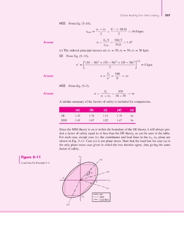
                                               Since the MSS theory is on or within the boundary of the DE theory, it will always pre-
                                               dict a factor of safety equal to or less than the DE theory, as can be seen in the table.
                                               For each case, except case (e), the coordinates and load lines in the σ A ,σ B plane are
                                               shown in Fig. 5–11. Case (e) is not plane stress. Note that the load line for case (a) is
                                               the only plane stress case given in which the two theories agree, thus giving the same
                                               factor of safety.

                       Figure 5–11                           B
                                                                        (a)
                       Load lines for Example 5–1.         S y


                                                                            (b)
                                                                   B
                                                                  A
                                                –S y
                                                                      S y      A
                                                                            (c)

                                                                        DE
                                                            –S y        MSS
                                                                        Load lines
                                                   (d)
   247   248   249   250   251   252   253   254   255   256   257