Page 257 - Shigley's Mechanical Engineering Design
P. 257

bud29281_ch05_212-264.qxd  11/27/2009  6:46 pm  Page 232 pinnacle s-171:Desktop Folder:Temp Work:Don't Delete (Jobs):MHDQ196/Budynas:


                 232    Mechanical Engineering Design
                                              For ductile materials with unequal yield strengths, S yt in tension and S yc in com-
                                          pression, the Mohr theory is the best available. However, the theory requires the results
                                          from three separate modes of tests, graphical construction of the failure locus, and fit-
                                          ting the largest Mohr’s circle to the failure locus. The alternative to this is to use the
                                          Coulomb-Mohr theory, which requires only the tensile and compressive yield strengths
                                          and is easily dealt with in equation form.


                        EXAMPLE 5–3       This example illustrates the use of a failure theory to determine the strength of a mechan-
                                          ical element or component. The example may also clear up any confusion existing
                                          between the phrases strength of a machine part, strength of a material, and strength of
                                          a part at a point.
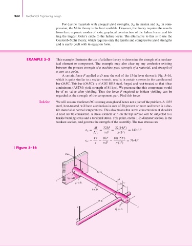
                                              A certain force F applied at D near the end of the 15-in lever shown in Fig. 5–16,
                                          which is quite similar to a socket wrench, results in certain stresses in the cantilevered
                                          bar OABC. This bar (OABC) is of AISI 1035 steel, forged and heat-treated so that it has
                                          a minimum (ASTM) yield strength of 81 kpsi. We presume that this component would
                                          be of no value after yielding. Thus the force  F required to initiate yielding can be
                                          regarded as the strength of the component part. Find this force.
                                Solution  We will assume that lever DC is strong enough and hence not a part of the problem. A 1035
                                          steel, heat-treated, will have a reduction in area of 50 percent or more and hence is a duc-
                                          tile material at normal temperatures. This also means that stress concentration at shoulder
                                          A need not be considered. A stress element at A on the top surface will be subjected to a
                                          tensile bending stress and a torsional stress. This point, on the 1-in-diameter section, is the
                                          weakest section, and governs the strength of the assembly. The two stresses are
                                                                 M    32M    32(14F)
                                                            σ x =   =      =         = 142.6F
                                                                                  3
                                                                I/c    πd 3    π(1 )
                                                                 Tr   16T    16(15F)
                                                           τ zx =   =     =         = 76.4F
                                                                                 3
                                                                 J    πd 3    π(1 )
                  Figure 5–16                        y
                                               2 in


                                                     O
                                                         A
                                                                   12 in
                                                 1
                                                 1 -in D.
                                          z      2                             B
                                                      1  -in R.                    C
                                                      8                        2 in
                                                               1-in D.


                                                                   15 in
                                                                                           x
                                                       F
                                                                              1
                                                                             1 -in D.
                                                                              2
                                                      D
   252   253   254   255   256   257   258   259   260   261   262