Page 254 - Shigley's Mechanical Engineering Design
P. 254

bud29281_ch05_212-264.qxd  11/27/2009  6:46 pm  Page 229 pinnacle s-171:Desktop Folder:Temp Work:Don't Delete (Jobs):MHDQ196/Budynas:


                                                                                     Failures Resulting from Static Loading  229
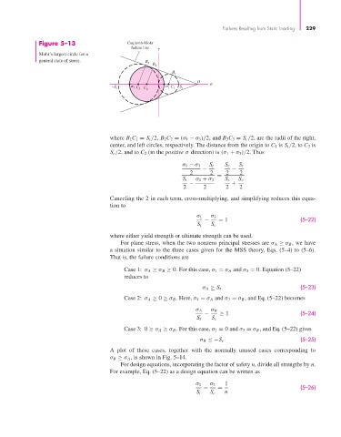
                       Figure 5–13                   Coulomb-Mohr
                                                      failure line
                       Mohr’s largest circle for a
                       general state of stress.            B
                                                            3  B 2
                                                                    B
                                                                     1
                                                                            O
                                                –S c    C 3  C 2    C 1  S t
                                                       3
                                                                   1


                                               where B 1C 1 = S t /2, B 2 C 2 = (σ 1 − σ 3 )/2, and B 3C 3 = S c /2, are the radii of the right,
                                               center, and left circles, respectively. The distance from the origin to C 1 is S t /2, to C 3 is
                                               S c /2, and to C 2 (in the positive σ direction) is (σ 1 + σ 3 )/2. Thus
                                                                       σ 1 − σ 3  S t  S c  S t
                                                                              −         −
                                                                          2      2    2    2
                                                                                   =
                                                                       S t  σ 1 + σ 3  S t  S c
                                                                          −             +
                                                                        2     2       2    2
                                               Canceling the 2 in each term, cross-multiplying, and simplifying reduces this equa-
                                               tion to
                                                                            σ 1  σ 3
                                                                               −    = 1                        (5–22)
                                                                            S t  S c
                                               where either yield strength or ultimate strength can be used.
                                                  For plane stress, when the two nonzero principal stresses are σ A ≥ σ B , we have
                                               a situation similar to the three cases given for the MSS theory, Eqs. (5–4) to (5–6).
                                               That is, the failure conditions are
                                                    Case 1: σ A ≥ σ B ≥ 0. For this case, σ 1 = σ A and σ 3 = 0. Equation (5–22)
                                                    reduces to
                                                                                                               (5–23)
                                                                              σ A ≥ S t
                                                    Case 2: σ A ≥ 0 ≥ σ B . Here, σ 1 = σ A and σ 3 = σ B , and Eq. (5–22) becomes

                                                                            σ A  σ B
                                                                               −    ≥ 1                        (5–24)
                                                                            S t  S c
                                                    Case 3: 0 ≥ σ A ≥ σ B . For this case, σ 1 = 0 and σ 3 = σ B , and Eq. (5–22) gives
                                                                                                               (5–25)
                                                                             σ B ≤−S c
                                               A plot of these cases, together with the normally unused cases corresponding to
                                               σ B ≥ σ A , is shown in Fig. 5–14.
                                                  For design equations, incorporating the factor of safety n, divide all strengths by n.
                                               For example, Eq. (5–22) as a design equation can be written as

                                                                            σ 1  σ 3  1
                                                                              −    =                           (5–26)
                                                                            S t  S c  n
   249   250   251   252   253   254   255   256   257   258   259