
Page 255 - Shigley's Mechanical Engineering Design
P. 255
bud29281_ch05_212-264.qxd 11/27/2009 6:46 pm Page 230 pinnacle s-171:Desktop Folder:Temp Work:Don't Delete (Jobs):MHDQ196/Budynas:
230 Mechanical Engineering Design
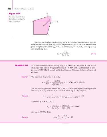
Figure 5–14 B
S
Plot of the Coulomb-Mohr t
theory failure envelope for
Nonfailure region
plane stress states. A
–S c S t
–S c
Since for the Coulomb-Mohr theory we do not need the torsional shear strength
circle we can deduce it from Eq. (5–22). For pure shear τ, σ 1 =−σ 3 = τ. The torsional
yield strength occurs when τ max = S sy . Substituting σ 1 =−σ 3 = S sy into Eq. (5–22)
and simplifying gives
S yt S yc
S sy = (5–27)
S yt + S yc
EXAMPLE 5–2 A 25-mm-diameter shaft is statically torqued to 230 N · m. It is made of cast 195-T6
aluminum, with a yield strength in tension of 160 MPa and a yield strength in com-
pression of 170 MPa. It is machined to final diameter. Estimate the factor of safety of
the shaft.
Solution The maximum shear stress is given by
16T 16(230) 6 2
τ = = = 75 10 N/m = 75 MPa
πd 3 π 25 10 −3 3
The two nonzero principal stresses are 75 and −75 MPa, making the ordered principal
stresses σ 1 = 75, σ 2 = 0, and σ 3 =−75 MPa. From Eq. (5–26), for yield,
1 1
Answer n = = = 1.10
σ 1 /S yt − σ 3 /S yc 75/160 − (−75)/170
Alternatively, from Eq. (5–27),
S yt S yc 160(170)
S sy = = = 82.4MPa
S yt + S yc 160 + 170
and τ max = 75 MPa. Thus,
Answer n = S sy = 82.4 = 1.10
τ max 75