
Page 253 - Shigley's Mechanical Engineering Design
P. 253
bud29281_ch05_212-264.qxd 11/27/2009 6:46 pm Page 228 pinnacle s-171:Desktop Folder:Temp Work:Don't Delete (Jobs):MHDQ196/Budynas:
228 Mechanical Engineering Design
5–6 Coulomb-Mohr Theory for Ductile Materials
Not all materials have compressive strengths equal to their corresponding tensile
values. For example, the yield strength of magnesium alloys in compression may be
as little as 50 percent of their yield strength in tension. The ultimate strength of gray
cast irons in compression varies from 3 to 4 times greater than the ultimate tensile
strength. So, in this section, we are primarily interested in those theories that can
be used to predict failure for materials whose strengths in tension and compression
are not equal.
Historically, the Mohr theory of failure dates to 1900, a date that is relevant to its
presentation. There were no computers, just slide rules, compasses, and French curves.
Graphical procedures, common then, are still useful today for visualization. The idea of
Mohr is based on three “simple” tests: tension, compression, and shear, to yielding if the
material can yield, or to rupture. It is easier to define shear yield strength as S sy than it is
to test for it.
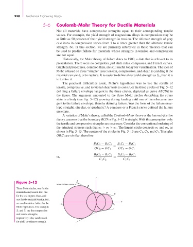
The practical difficulties aside, Mohr’s hypothesis was to use the results of
tensile, compressive, and torsional shear tests to construct the three circles of Fig. 5–12
defining a failure envelope tangent to the three circles, depicted as curve ABCDE in
the figure. The argument amounted to the three Mohr circles describing the stress
state in a body (see Fig. 3–12) growing during loading until one of them became tan-
gent to the failure envelope, thereby defining failure. Was the form of the failure enve-
lope straight, circular, or quadratic? A compass or a French curve defined the failure
envelope.
A variation of Mohr’s theory, called the Coulomb-Mohr theory or the internal-friction
theory, assumes that the boundary BCD in Fig. 5–12 is straight. With this assumption only
the tensile and compressive strengths are necessary. Consider the conventional ordering of
the principal stresses such that σ 1 ≥ σ 2 ≥ σ 3 . The largest circle connects σ 1 and σ 3,as
shown in Fig. 5–13. The centers of the circles in Fig. 5–13 are C 1 , C 2 , and C 3 . Triangles
OB i C i are similar, therefore
B 2 C 2 − B 1 C 1 B 3 C 3 − B 1 C 1
=
OC 2 − OC 1 OC 3 − OC 1
B 2 C 2 − B 1 C 1 B 3 C 3 − B 1 C 1
or, =
C 1 C 2 C 1 C 3
Figure 5–12 A
Mohr failure curve
B
Three Mohr circles, one for the
uniaxial compression test, one C D
for the test in pure shear, and E
one for the uniaxial tension test,
are used to define failure by the –S c S t
Mohr hypothesis. The strengths
S c and S t are the compressive
and tensile strengths,
respectively; they can be used
for yield or ultimate strength.