
Page 266 - Shigley's Mechanical Engineering Design
P. 266
bud29281_ch05_212-264.qxd 12/7/09 7:22PM Page 241 ntt G4 Mac OS 9.2:Desktop Folder:MHDQ196/Budynas:
Failures Resulting from Static Loading 241
Figure 5–22 y
b
x
a
Note that when a = b, the ellipse becomes a circle and Eq. (5–33) gives a stress-
concentration factor of 3. This agrees with the well-known result for an infinite plate with
a circular hole (see Table A–15–1). For a fine crack, b/a → 0, and Eq. (5–34) predicts
that (σ y ) max →∞. However, on a microscopic level, an infinitely sharp crack is a
hypothetical abstraction that is physically impossible, and when plastic deformation
occurs, the stress will be finite at the crack tip.
Griffith showed that the crack growth occurs when the energy release rate from
applied loading is greater than the rate of energy for crack growth. Crack growth can be
stable or unstable. Unstable crack growth occurs when the rate of change of the energy
release rate relative to the crack length is equal to or greater than the rate of change of
the crack growth rate of energy. Griffith’s experimental work was restricted to brittle
materials, namely glass, which pretty much confirmed his surface energy hypothesis.
However, for ductile materials, the energy needed to perform plastic work at the crack
tip is found to be much more crucial than surface energy.
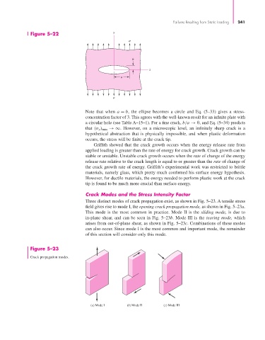
Crack Modes and the Stress Intensity Factor
Three distinct modes of crack propagation exist, as shown in Fig. 5–23. A tensile stress
field gives rise to mode I, the opening crack propagation mode, as shown in Fig. 5–23a.
This mode is the most common in practice. Mode II is the sliding mode, is due to
in-plane shear, and can be seen in Fig. 5–23b. Mode III is the tearing mode, which
arises from out-of-plane shear, as shown in Fig. 5–23c. Combinations of these modes
can also occur. Since mode I is the most common and important mode, the remainder
of this section will consider only this mode.
Figure 5–23
Crack propagation modes.
(a) Mode I (b) Mode II (c) Mode III