
Page 268 - Shigley's Mechanical Engineering Design
P. 268
bud29281_ch05_212-264.qxd 11/27/2009 9:05 pm Page 243 pinnacle s-171:Desktop Folder:Temp Work:Don't Delete (Jobs):MHDQ196/Budynas:
Failures Resulting from Static Loading 243
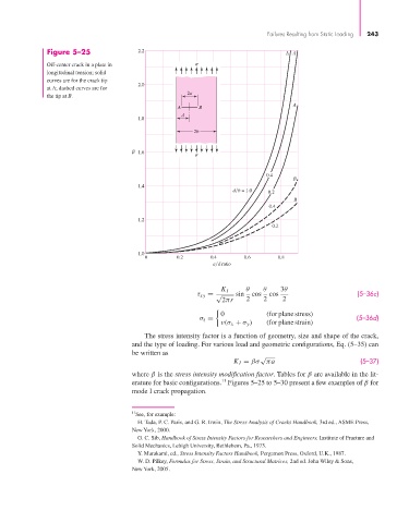
Figure 5–25 2.2 AA
Off-center crack in a plate in
longitudinal tension; solid
curves are for the crack tip
2.0
at A; dashed curves are for
2a
the tip at B.
A
A B
d
1.8
2b
1.6
0.4
B
1.4
d b = 1.0 0.2
B
0.4
1.2
0.2
1.0
0 0.2 0.4 0.6 0.8
a d ratio
K I θ θ 3θ
τ xy = √ sin cos cos (5–36c)
2πr 2 2 2
0 (for plane stress)
σ z = (5–36d)
ν(σ x + σ y ) (for plane strain)
The stress intensity factor is a function of geometry, size and shape of the crack,
and the type of loading. For various load and geometric configurations, Eq. (5–35) can
be written as
√
K I = βσ πa (5–37)
where β is the stress intensity modification factor. Tables for β are available in the lit-
11
erature for basic configurations. Figures 5–25 to 5–30 present a few examples of β for
mode I crack propagation.
11 See, for example:
H. Tada, P. C. Paris, and G. R. Irwin, The Stress Analysis of Cracks Handbook, 3rd ed., ASME Press,
New York, 2000.
G. C. Sib, Handbook of Stress Intensity Factors for Researchers and Engineers, Institute of Fracture and
Solid Mechanics, Lehigh University, Bethlehem, Pa., 1973.
Y. Murakami, ed., Stress Intensity Factors Handbook, Pergamon Press, Oxford, U.K., 1987.
W. D. Pilkey, Formulas for Stress, Strain, and Structural Matrices, 2nd ed. John Wiley & Sons,
New York, 2005.