
Page 267 - Shigley's Mechanical Engineering Design
P. 267
bud29281_ch05_212-264.qxd 12/7/09 7:23PM Page 242 ntt G4 Mac OS 9.2:Desktop Folder:MHDQ196/Budynas:
242 Mechanical Engineering Design
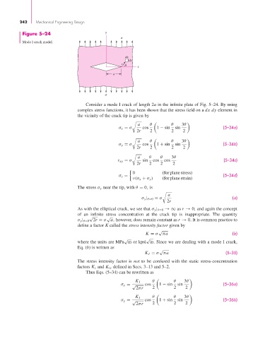
Figure 5–24 y
Mode I crack model.
dx
dy
r
x
a
Consider a mode I crack of length 2a in the infinite plate of Fig. 5–24. By using
complex stress functions, it has been shown that the stress field on a dx dy element in
the vicinity of the crack tip is given by
a θ θ 3θ
σ x = σ cos 1 − sin sin (5–34a)
2r 2 2 2
a θ θ 3θ
σ y = σ cos 1 + sin sin (5–34b)
2r 2 2 2
a θ θ 3θ
τ xy = σ sin cos cos (5–34c)
2r 2 2 2
0 (for plane stress)
σ z = (5–34d)
ν(σ x + σ y ) (for plane strain)
The stress σ y near the tip, with θ = 0, is
a
σ y | θ=0 = σ (a)
2r
As with the elliptical crack, we see that σ y | θ=0 →∞ as r → 0, and again the concept
of an infinite stress concentration at the crack tip is inappropriate. The quantity
√ √
σ y | θ=0 2r = σ a, however, does remain constant as r → 0. It is common practice to
define a factor K called the stress intensity factor given by
√
K = σ πa (b)
√ √
where the units are MPa m or kpsi in. Since we are dealing with a mode I crack,
Eq. (b) is written as
√
K I = σ πa (5–35)
The stress intensity factor is not to be confused with the static stress-concentration
factors K t and K ts defined in Secs. 3–13 and 5–2.
Thus Eqs. (5–34) can be rewritten as
θ θ 3θ
K I
σ x = √ cos 1 − sin sin (5–36a)
2πr 2 2 2
θ θ 3θ
K I
σ y = √ cos 1 + sin sin (5–36b)
2πr 2 2 2