
Page 270 - Shigley's Mechanical Engineering Design
P. 270
bud29281_ch05_212-264.qxd 11/27/2009 6:46 pm Page 245 pinnacle s-171:Desktop Folder:Temp Work:Don't Delete (Jobs):MHDQ196/Budynas:
Failures Resulting from Static Loading 245
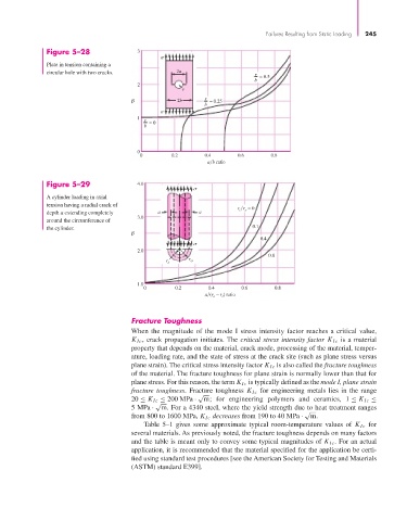
Figure 5–28 3
Plate in tension containing a
circular hole with two cracks. 2a
r = 0.5
b
2
r
2b r = 0.25
b
1
r = 0
b
0
0 0.2 0.4 0.6 0.8
a b ratio
Figure 5–29 4.0
A cylinder loading in axial
tension having a radial crack of
r r = 0
depth a extending completely a a i o
3.0
around the circumference of
the cylinder. 0.1
0.4
2.0
0.8
r i r o
1.0
0 0.2 0.4 0.6 0.8
a (r – r ) ratio
o i
Fracture Toughness
When the magnitude of the mode I stress intensity factor reaches a critical value,
K Ic , crack propagation initiates. The critical stress intensity factor K Ic is a material
property that depends on the material, crack mode, processing of the material, temper-
ature, loading rate, and the state of stress at the crack site (such as plane stress versus
plane strain). The critical stress intensity factor K Ic is also called the fracture toughness
of the material. The fracture toughness for plane strain is normally lower than that for
plane stress. For this reason, the term K Ic is typically defined as the mode I, plane strain
fracture toughness. Fracture toughness K Ic for engineering metals lies in the range
√
20 ≤ K Ic ≤ 200 MPa · m; for engineering polymers and ceramics, 1 ≤ K Ic ≤
√
5 MPa · m. For a 4340 steel, where the yield strength due to heat treatment ranges
√
from 800 to 1600 MPa, K Ic decreases from 190 to 40 MPa · m.
Table 5–1 gives some approximate typical room-temperature values of K Ic for
several materials. As previously noted, the fracture toughness depends on many factors
and the table is meant only to convey some typical magnitudes of K Ic . For an actual
application, it is recommended that the material specified for the application be certi-
fied using standard test procedures [see the American Society for Testing and Materials
(ASTM) standard E399].