Page 313 - Shigley's Mechanical Engineering Design
P. 313

bud29281_ch06_265-357.qxd  12/02/2009  6:49 pm  Page 288 pinnacle s-171:Desktop Folder:Temp Work:Don't Delete (Jobs):MHDQ196/Budynas:


                 288   Mechanical Engineering Design
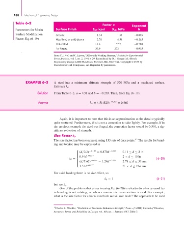
                  Table 6–2
                                                                         Factor a          Exponent
                  Parameters for Marin     Surface Finish         S ut, kpsi  S ut, MPa        b
                  Surface Modification      Ground                    1.34         1.58      −0.085
                  Factor, Eq. (6–19)       Machined or cold-drawn    2.70         4.51      −0.265

                                           Hot-rolled               14.4         57.7       −0.718
                                           As-forged                39.9        272.        −0.995

                                          From C.J. Noll and C. Lipson, “Allowable Working Stresses,” Society for Experimental
                                          Stress Analysis, vol. 3, no. 2, 1946 p. 29. Reproduced by O.J. Horger (ed.) Metals
                                          Engineering Design ASME Handbook, McGraw-Hill, New York. Copyright © 1953 by
                                          The McGraw-Hill Companies, Inc. Reprinted by permission.


                        EXAMPLE 6–3       A steel has a minimum ultimate strength of 520 MPa and a machined surface.
                                          Estimate k a .

                                Solution  From Table 6–2, a = 4.51 and b =−0.265. Then, from Eq. (6–19)

                                Answer                           k a = 4.51(520) −0.265  = 0.860


                                              Again, it is important to note that this is an approximation as the data is typically
                                          quite scattered. Furthermore, this is not a correction to take lightly. For example, if in
                                          the previous example the steel was forged, the correction factor would be 0.540, a sig-
                                          nificant reduction of strength.

                                          Size Factor k b
                                                                                             15
                                          The size factor has been evaluated using 133 sets of data points. The results for bend-
                                          ing and torsion may be expressed as
                                                        ⎧       −0.107       −0.107
                                                        ⎪ (d/0.3)    = 0.879d        0.11 ≤ d ≤ 2in
                                                        ⎪
                                                        ⎪
                                                          0.91d                      2 < d ≤ 10 in
                                                        ⎨      −0.157
                                                    k b =                                                 (6–20)
                                                        ⎪ (d/7.62) −0.107  = 1.24d −0.107  2.79 ≤ d ≤ 51 mm
                                                        ⎪
                                                        ⎪
                                                        ⎩      −0.157
                                                          1.51d                      51 < d ≤ 254 mm
                                          For axial loading there is no size effect, so
                                                                          k b = 1                          (6–21)
                                          but see k c .
                                              One of the problems that arises in using Eq. (6–20) is what to do when a round bar
                                          in bending is not rotating, or when a noncircular cross section is used. For example,
                                          what is the size factor for a bar 6 mm thick and 40 mm wide? The approach to be used


                                          15 Charles R. Mischke, “Prediction of Stochastic Endurance Strength,” Trans. of ASME, Journal of Vibration,
                                          Acoustics, Stress, and Reliability in Design, vol. 109, no. 1, January 1987, Table 3.
   308   309   310   311   312   313   314   315   316   317   318