
Page 315 - Shigley's Mechanical Engineering Design
P. 315
bud29281_ch06_265-357.qxd 11/30/2009 4:23 pm Page 290 pinnacle s-171:Desktop Folder:Temp Work:Don't Delete (Jobs):MHDQ196/Budynas:
290 Mechanical Engineering Design
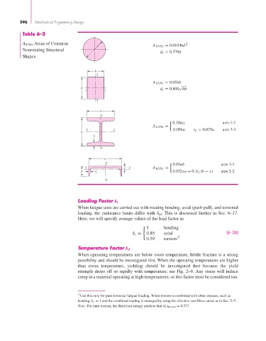
Table 6–3
A 0.95σ Areas of Common 2
d A 0.95σ = 0.01046d
Nonrotating Structural
d e = 0.370d
Shapes
b
2
A 0.95σ = 0.05hb
√
h d e = 0.808 hb
1 1
2
a
1
0.10at f axis 1-1
A 0.95σ =
2 2 0.05ba t f > 0.025a axis 2-2
b
t f
1
a
1 0.05ab axis 1-1
2 x 2 A 0.95σ =
b t f 0.052xa + 0.1t f (b − x) axis 2-2
1
Loading Factor k c
When fatigue tests are carried out with rotating bending, axial (push-pull), and torsional
loading, the endurance limits differ with S ut . This is discussed further in Sec. 6–17.
Here, we will specify average values of the load factor as
1 bending
k c = 0.85 axial (6–26)
0.59 torsion 17
Temperature Factor k d
When operating temperatures are below room temperature, brittle fracture is a strong
possibility and should be investigated first. When the operating temperatures are higher
than room temperature, yielding should be investigated first because the yield
strength drops off so rapidly with temperature; see Fig. 2–9. Any stress will induce
creep in a material operating at high temperatures; so this factor must be considered too.
17 Use this only for pure torsional fatigue loading. When torsion is combined with other stresses, such as
bending, k c = 1 and the combined loading is managed by using the effective von Mises stress as in Sec. 5–5.
Note: For pure torsion, the distortion energy predicts that (k c) torsion = 0.577.