
Page 318 - Shigley's Mechanical Engineering Design
P. 318
bud29281_ch06_265-357.qxd 11/30/2009 4:23 pm Page 293 pinnacle s-171:Desktop Folder:Temp Work:Don't Delete (Jobs):MHDQ196/Budynas:
Fatigue Failure Resulting from Variable Loading 293
Table 6–5
Reliability, % Transformation Variate z a Reliability Factor k e
Reliability Factors k e 50 0 1.000
Corresponding to 90 1.288 0.897
8 Percent Standard 95 1.645 0.868
Deviation of the 99 2.326 0.814
Endurance Limit 99.9 3.091 0.753
99.99 3.719 0.702
99.999 4.265 0.659
99.9999 4.753 0.620
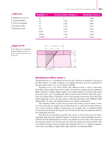
Figure 6–19 S (case)
e
The failure of a case-hardened or
part in bending or torsion. In
this example, failure occurs in Case
the core.
Core
(core)
S e
Miscellaneous-Effects Factor k f
Though the factor k f is intended to account for the reduction in endurance limit due to
all other effects, it is really intended as a reminder that these must be accounted for,
because actual values of k f are not always available.
Residual stresses may either improve the endurance limit or affect it adversely.
Generally, if the residual stress in the surface of the part is compression, the endurance
limit is improved. Fatigue failures appear to be tensile failures, or at least to be caused
by tensile stress, and so anything that reduces tensile stress will also reduce the possi-
bility of a fatigue failure. Operations such as shot peening, hammering, and cold rolling
build compressive stresses into the surface of the part and improve the endurance limit
significantly. Of course, the material must not be worked to exhaustion.
The endurance limits of parts that are made from rolled or drawn sheets or bars,
as well as parts that are forged, may be affected by the so-called directional character-
istics of the operation. Rolled or drawn parts, for example, have an endurance limit
in the transverse direction that may be 10 to 20 percent less than the endurance limit in
the longitudinal direction.
Parts that are case-hardened may fail at the surface or at the maximum core radius,
depending upon the stress gradient. Figure 6–19 shows the typical triangular stress dis-
tribution of a bar under bending or torsion. Also plotted as a heavy line in this figure are
the endurance limits S e for the case and core. For this example the endurance limit of the
core rules the design because the figure shows that the stress σ or τ, whichever applies,
at the outer core radius, is appreciably larger than the core endurance limit.