
Page 374 - Shigley's Mechanical Engineering Design
P. 374
bud29281_ch06_265-357.qxd 12/9/09 7:19PM Page 349 ntt 203:MHDQ196:bud29281:0073529281:bud29281_pagefiles:
Fatigue Failure Resulting from Variable Loading 349
3
6–14 A rectangular bar is cut from an AISI 1020 cold-drawn steel flat. The bar is 2.5 in wide by in
8
thick and has a 0.5-in-dia. hole drilled through the center as depicted in Table A–15–1. The bar
is concentrically loaded in push-pull fatigue by axial forces F a , uniformly distributed across
the width. Using a design factor of n d = 2, estimate the largest force F a that can be applied
ignoring column action.
6–15 A solid round bar with diameter of 2 in has a groove cut to a diameter of 1.8 in, with a radius of
0.1 in. The bar is not rotating. The bar is loaded with a repeated bending load that causes the
bending moment at the groove to fluctuate between 0 and 25 000 lbf · in. The bar is hot-rolled
AISI 1095, but the groove has been machined. Determine the factor of safety for fatigue based
on infinite life and the factor of safety for yielding.
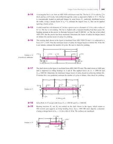
6–16 The rotating shaft shown in the figure is machined from AISI 1020 CD steel. It is subjected to a
force of F = 6 kN. Find the minimum factor of safety for fatigue based on infinite life. If the life
is not infinite, estimate the number of cycles. Be sure to check for yielding.
500
F 175
25 D. 35 D. 3 R. 50 D. 25 D.
Problem 6–16
Dimensions in millimeters
20 20
20 180 280 20
6–17 The shaft shown in the figure is machined from AISI 1040 CD steel. The shaft rotates at 1600 rpm
and is supported in rolling bearings at A and B. The applied forces are F 1 = 2500 lbf and
F 2 = 1000 lbf. Determine the minimum fatigue factor of safety based on achieving infinite life.
If infinite life is not predicted, estimate the number of cycles to failure. Also check for yielding.
8 in 8 in 8 in
F 1 F 2
1
1 1 4 in 1 5 8 in 1 7 8 in 1 3 4 in 1 in
4
Problem 6–17
3 in
10 in 10 in
1 in 1
2 2 in
A All fillets 1 in R. B
16
6–18 Solve Prob. 6–17 except with forces F 1 = 1200 lbf and F 2 = 2400 lbf.
6–19 Bearing reactions R 1 and R 2 are exerted on the shaft shown in the figure, which rotates at
950 rev/min and supports an 8-kip bending force. Use a 1095 HR steel. Specify a diameter
d using a design factor of n d = 1.6 for a life of 10 hr. The surfaces are machined.
F = 8 kip
10 in 5 in 5 in
d/5 R.
Problem 6–19
d R 1 1.4 d R d
d/10 R. 2
1 in