
Page 447 - Shigley's Mechanical Engineering Design
P. 447
bud29281_ch08_409-474.qxd 12/16/2009 7:11 pm Page 422 pinnacle 203:MHDQ196:bud29281:0073529281:bud29281_pagefiles:
422 Mechanical Engineering Design
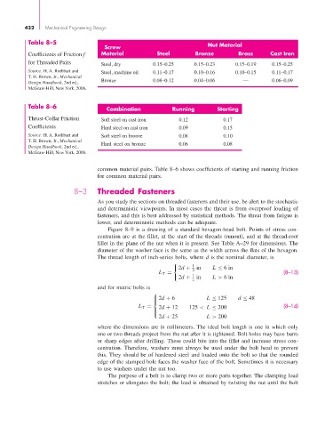
Table 8–5
Screw Nut Material
Coefficients of Friction f Material Steel Bronze Brass Cast Iron
for Threaded Pairs Steel, dry 0.15–0.25 0.15–0.23 0.15–0.19 0.15–0.25
Source: H. A. Rothbart and Steel, machine oil 0.11–0.17 0.10–0.16 0.10–0.15 0.11–0.17
T. H. Brown, Jr., Mechanical
Design Handbook, 2nd ed., Bronze 0.08–0.12 0.04–0.06 — 0.06–0.09
McGraw-Hill, New York, 2006.
Table 8–6 Combination Running Starting
Thrust-Collar Friction Soft steel on cast iron 0.12 0.17
Coefficients Hard steel on cast iron 0.09 0.15
Source: H. A. Rothbart and Soft steel on bronze 0.08 0.10
T. H. Brown, Jr., Mechanical Hard steel on bronze 0.06 0.08
Design Handbook, 2nd ed.,
McGraw-Hill, New York, 2006.
common material pairs. Table 8–6 shows coefficients of starting and running friction
for common material pairs.
8–3 Threaded Fasteners
As you study the sections on threaded fasteners and their use, be alert to the stochastic
and deterministic viewpoints. In most cases the threat is from overproof loading of
fasteners, and this is best addressed by statistical methods. The threat from fatigue is
lower, and deterministic methods can be adequate.
Figure 8–9 is a drawing of a standard hexagon-head bolt. Points of stress con-
centration are at the fillet, at the start of the threads (runout), and at the thread-root
fillet in the plane of the nut when it is present. See Table A–29 for dimensions. The
diameter of the washer face is the same as the width across the flats of the hexagon.
The thread length of inch-series bolts, where d is the nominal diameter, is
1
2d + 4 in L ≤ 6in
L T = 1 (8–13)
2d + 2 in L > 6in
and for metric bolts is
⎧
⎪ 2d + 6 L ≤ 125 d ≤ 48
⎨
L T = 2d + 12 125 < L ≤ 200 (8–14)
⎪
⎩
2d + 25 L > 200
where the dimensions are in millimeters. The ideal bolt length is one in which only
one or two threads project from the nut after it is tightened. Bolt holes may have burrs
or sharp edges after drilling. These could bite into the fillet and increase stress con-
centration. Therefore, washers must always be used under the bolt head to prevent
this. They should be of hardened steel and loaded onto the bolt so that the rounded
edge of the stamped hole faces the washer face of the bolt. Sometimes it is necessary
to use washers under the nut too.
The purpose of a bolt is to clamp two or more parts together. The clamping load
stretches or elongates the bolt; the load is obtained by twisting the nut until the bolt