
Page 450 - Shigley's Mechanical Engineering Design
P. 450
bud29281_ch08_409-474.qxd 12/19/2009 11:34 am Page 425 pinnacle 203:MHDQ196:bud29281:0073529281:bud29281_pagefiles:
Screws, Fasteners, and the Design of Nonpermanent Joints 425
Figure 8–13 P P
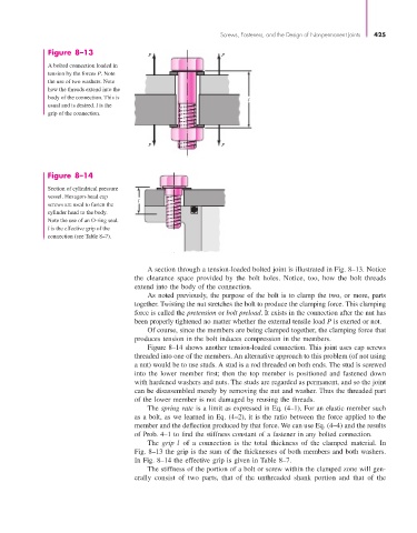
A bolted connection loaded in
tension by the forces P. Note
the use of two washers. Note
how the threads extend into the
body of the connection. This is l
usual and is desired. l is the
grip of the connection.
P P
Figure 8–14
Section of cylindrical pressure
vessel. Hexagon-head cap
l
screws are used to fasten the
cylinder head to the body.
Note the use of an O-ring seal.
l is the effective grip of the
connection (see Table 8–7).
A section through a tension-loaded bolted joint is illustrated in Fig. 8–13. Notice
the clearance space provided by the bolt holes. Notice, too, how the bolt threads
extend into the body of the connection.
As noted previously, the purpose of the bolt is to clamp the two, or more, parts
together. Twisting the nut stretches the bolt to produce the clamping force. This clamping
force is called the pretension or bolt preload. It exists in the connection after the nut has
been properly tightened no matter whether the external tensile load P is exerted or not.
Of course, since the members are being clamped together, the clamping force that
produces tension in the bolt induces compression in the members.
Figure 8–14 shows another tension-loaded connection. This joint uses cap screws
threaded into one of the members. An alternative approach to this problem (of not using
a nut) would be to use studs. A stud is a rod threaded on both ends. The stud is screwed
into the lower member first; then the top member is positioned and fastened down
with hardened washers and nuts. The studs are regarded as permanent, and so the joint
can be disassembled merely by removing the nut and washer. Thus the threaded part
of the lower member is not damaged by reusing the threads.
The spring rate is a limit as expressed in Eq. (4–1). For an elastic member such
as a bolt, as we learned in Eq. (4–2), it is the ratio between the force applied to the
member and the deflection produced by that force. We can use Eq. (4–4) and the results
of Prob. 4–1 to find the stiffness constant of a fastener in any bolted connection.
The grip l of a connection is the total thickness of the clamped material. In
Fig. 8–13 the grip is the sum of the thicknesses of both members and both washers.
In Fig. 8–14 the effective grip is given in Table 8–7.
The stiffness of the portion of a bolt or screw within the clamped zone will gen-
erally consist of two parts, that of the unthreaded shank portion and that of the