
Page 453 - Shigley's Mechanical Engineering Design
P. 453
bud29281_ch08_409-474.qxd 12/16/2009 7:11 pm Page 428 pinnacle 203:MHDQ196:bud29281:0073529281:bud29281_pagefiles:
428 Mechanical Engineering Design
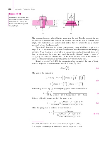
Figure 8–15 x D
Compression of a member with
the equivalent elastic properties y
represented by a frustum of a d w t x y
hollow cone. Here, l represents 2 l t
the grip length. d
dx d
x
(a) (b)
The pressure, however, falls off farther away from the bolt. Thus Ito suggests the use
of Rotscher’s pressure-cone method for stiffness calculations with a variable cone
angle. This method is quite complicated, and so here we choose to use a simpler
approach using a fixed cone angle.
Figure 8–15 illustrates the general cone geometry using a half-apex angle α. An
3
angle α = 45 has been used, but Little reports that this overestimates the clamping
◦
stiffness. When loading is restricted to a washer-face annulus (hardened steel, cast
4
iron, or aluminum), the proper apex angle is smaller. Osgood reports a range of
25 ≤ α ≤ 33 for most combinations. In this book we shall use α = 30 except in
◦
◦
◦
cases in which the material is insufficient to allow the frusta to exist.
Referring now to Fig. 8–15b, the contraction of an element of the cone of thick-
ness dx subjected to a compressive force P is, from Eq. (4–3),
Pdx
dδ = (a)
EA
The area of the element is
2
d
D 2
2
A = π r − r 2 i = π x tan α + 2 − 2
o
(b)
D + d D − d
= π x tan α + x tan α +
2 2
Substituting this in Eq. (a) and integrating gives a total contraction of
P t dx
δ = (c)
π E 0 [x tan α + (D + d)/2][x tan α + (D − d)/2]
Using a table of integrals, we find the result to be
P (2t tan α + D − d)(D + d)
δ = ln (d)
π Ed tan α (2t tan α + D + d)(D − d)
Thus the spring rate or stiffness of this frustum is
P π Ed tan α
k = =
δ (2t tan α + D − d)(D + d) (8–19)
ln
(2t tan α + D + d)(D − d)
3 R. E. Little, “Bolted Joints: How Much Give?” Machine Design, Nov. 9, 1967.
4 C. C. Osgood, “Saving Weight on Bolted Joints,” Machine Design, Oct. 25, 1979.