Page 518 - Shigley's Mechanical Engineering Design
P. 518

bud29281_ch09_475-516.qxd  12/16/2009  7:12 pm  Page 492 pinnacle 203:MHDQ196:bud29281:0073529281:bud29281_pagefiles:


                 492   Mechanical Engineering Design
                                  9–6     Static Loading

                                          Some examples of statically loaded joints are useful in comparing and contrasting the
                                          conventional method of analysis and the welding code methodology.


                                            1
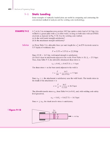
                        EXAMPLE 9–2       A  -in by 2-in rectangular-cross-section 1015 bar carries a static load of 16.5 kip. It is
                                            2
                                                                    3
                                          welded to a gusset plate with a  -in fillet weld 2 in long on both sides with an E70XX
                                                                    8
                                          electrode as depicted in Fig. 9–18. Use the welding code method.
                                          (a) Is the weld metal strength satisfactory?
                                          (b) Is the attachment strength satisfactory?
                                Solution  (a) From Table 9–6, allowable force per unit length for a  -in E70 electrode metal is
                                                                                          3
                                                                                          8
                                          5.57 kip/in of weldment; thus
                                                               F = 5.57l = 5.57(4) = 22.28 kip

                                          Since 22.28 > 16.5 kip, weld metal strength is satisfactory.
                                          (b) Check shear in attachment adjacent to the welds. From Table A–20, S y = 27.5 kpsi.
                                          Then, from Table 9–4, the allowable attachment shear stress is
                                                              τ all = 0.4S y = 0.4(27.5) = 11 kpsi

                                          The shear stress τ on the base metal adjacent to the weld is

                                                                    F      16.5
                                                               τ =     =          = 11 kpsi
                                                                   2hl   2(0.375)2
                                          Since τ all ≥ τ, the attachment is satisfactory near the weld beads. The tensile stress in
                                          the shank of the attachment σ is
                                                                     F    16.5
                                                                σ =    =       = 16.5 kpsi
                                                                    tl   (1/2)2
                                          The allowable tensile stress σ all , from Table 9–4, is 0.6S y and, with welding code safety
                                          level preserved,
                                                              σ all = 0.6S y = 0.6(27.5) = 16.5 kpsi

                                          Since σ ≤ σ all , the shank tensile stress is satisfactory.


                  Figure 9–18                                   1  in
                                                                2

                                                                    2 in            F = 16.5 kip
   513   514   515   516   517   518   519   520   521   522   523