
Page 519 - Shigley's Mechanical Engineering Design
P. 519
bud29281_ch09_475-516.qxd 12/16/2009 7:12 pm Page 493 pinnacle 203:MHDQ196:bud29281:0073529281:bud29281_pagefiles:
Welding, Bonding, and the Design of Permanent Joints 493
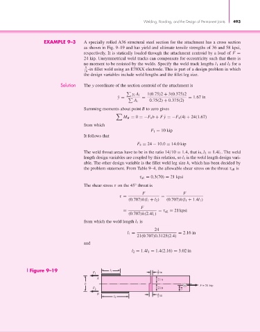
EXAMPLE 9–3 A specially rolled A36 structural steel section for the attachment has a cross section
as shown in Fig. 9–19 and has yield and ultimate tensile strengths of 36 and 58 kpsi,
respectively. It is statically loaded through the attachment centroid by a load of F =
24 kip. Unsymmetrical weld tracks can compensate for eccentricity such that there is
no moment to be resisted by the welds. Specify the weld track lengths l 1 and l 2 for a
5 -in fillet weld using an E70XX electrode. This is part of a design problem in which
16
the design variables include weld lengths and the fillet leg size.
Solution The y coordinate of the section centroid of the attachment is
1(0.75)2 + 3(0.375)2
y i A i
= = 1.67 in
¯ y =
A i 0.75(2) + 0.375(2)
Summing moments about point B to zero gives
M B = 0 =−F 1 b + F ¯y =−F 1 (4) + 24(1.67)
from which
F 1 = 10 kip
It follows that
F 2 = 24 − 10.0 = 14.0 kip
The weld throat areas have to be in the ratio 14/10 = 1.4, that is, l 2 = 1.4l 1 . The weld
length design variables are coupled by this relation, so l 1 is the weld length design vari-
able. The other design variable is the fillet weld leg size h, which has been decided by
the problem statement. From Table 9–4, the allowable shear stress on the throat τ all is
τ all = 0.3(70) = 21 kpsi
The shear stress τ on the 45° throat is
F F
τ = =
(0.707)h(l 1 + l 2 ) (0.707)h(l 1 + 1.4l 1 )
F
= = τ all = 21 kpsi
(0.707)h(2.4l 1 )
from which the weld length l 1 is
24
l 1 = = 2.16 in
21(0.707)0.3125(2.4)
and
l 2 = 1.4l 1 = 1.4(2.16) = 3.02 in
Figure 9–19 F 1 l 1 3 8 in
A
2 in
b
+ F = 24 kip
F 2 2 in y
B 3
l 2 4 in