
Page 514 - Shigley's Mechanical Engineering Design
P. 514
bud29281_ch09_475-516.qxd 12/16/2009 7:12 pm Page 489 pinnacle 203:MHDQ196:bud29281:0073529281:bud29281_pagefiles:
Welding, Bonding, and the Design of Permanent Joints 489
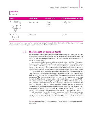
Table 9–2
Continued
Weld Throat Area Location of G Unit Second Moment of Area
8. b d 2
A = 1.414h(b d) x ¯ = b/2 I u = (3b + d )
6
y ¯ = d/2
G d
y
x
9. A = 1.414π ihr l u πr 3
G
r
*I u, unit second moment of area, is taken about a horizontal axis through G, the centroid of the weld group, h is weld size; the plane of the bending
couple is normal to the plane of the paper and parallel to the y-axis; all welds are of the same size.
9–5 The Strength of Welded Joints
The matching of the electrode properties with those of the parent metal is usually not
so important as speed, operator appeal, and the appearance of the completed joint. The
properties of electrodes vary considerably, but Table 9–3 lists the minimum properties
for some electrode classes.
It is preferable, in designing welded components, to select a steel that will result in a
fast, economical weld even though this may require a sacrifice of other qualities such as
machinability. Under the proper conditions, all steels can be welded, but best results will be
obtained if steels having a UNS specification between G10140 and G10230 are chosen.All
these steels have a tensile strength in the hot-rolled condition in the range of 60 to 70 kpsi.
The designer can choose factors of safety or permissible working stresses with more
confidence if he or she is aware of the values of those used by others. One of the best stan-
dards to use is the American Institute of Steel Construction (AISC) code for building
4
construction. The permissible stresses are now based on the yield strength of the mate-
rial instead of the ultimate strength, and the code permits the use of a variety of ASTM
structural steels having yield strengths varying from 33 to 50 kpsi. Provided the loading
is the same, the code permits the same stress in the weld metal as in the parent metal. For
these ASTM steels, S y = 0.5S u . Table 9–4 lists the formulas specified by the code for
calculating these permissible stresses for various loading conditions. The factors of safety
implied by this code are easily calculated. For tension, n = 1/0.60 = 1.67. For shear,
n = 0.577/0.40 = 1.44, using the distortion-energy theory as the criterion of failure.
It is important to observe that the electrode material is often the strongest material
present. If a bar of AISI 1010 steel is welded to one of 1018 steel, the weld metal is
actually a mixture of the electrode material and the 1010 and 1018 steels. Furthermore,
4 For a copy, either write the AISC, 400 N. Michigan Ave., Chicago, IL 60611, or contact on the Internet at
www.aisc.org.