Page 511 - Shigley's Mechanical Engineering Design
P. 511

bud29281_ch09_475-516.qxd  12/16/2009  7:12 pm  Page 486 pinnacle 203:MHDQ196:bud29281:0073529281:bud29281_pagefiles:


                 486   Mechanical Engineering Design
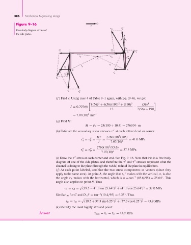
                  Figure 9–16
                                                               F
                                                                                  ′′
                  Free-body diagram of one of                              D      D
                  the side plates.


                                                                                      A
                                             ′    C                         ′
                                            C                               D              ′′
                                                                                     D    A
                                                        r C                r D
                                                                   O
                                                                          r A
                                                ′        r B
                                                B
                                                    B                                A
                                                ′′ C                          ′ A

                                           C


                                                   B    ′′ B
                                          (f ) Find J. Using case 4 of Table 9–1 again, with Eq. (9–6), we get

                                                                    3           2       3         4
                                                               8(56) + 6(56)(190) + (190)     (56)
                                                   J = 0.707(6)                          −
                                                                           12              2(56) + 190
                                                             6
                                                    = 7.07(10) mm 4
                                          (g) Find M:
                                                            M = Fl = 25(100 + 10.4) = 2760 N · m
                                          (h) Estimate the secondary shear stresses τ at each lettered end or corner:

                                                                                3
                                                                   Mr    2760(10) (105)
                                                                                      = 41.0MPa
                                                         τ = τ =      =
                                                          A    B                  6
                                                                    J      7.07(10)
                                                                          3
                                                                   2760(10) (95.6)
                                                                                 = 37.3MPa
                                                         τ = τ =
                                                               D
                                                          C
                                                                     7.07(10) 6
                                          (i) Draw the τ stress at each corner and end. See Fig. 9–16. Note that this is a free-body

                                          diagram of one of the side plates, and therefore the τ and τ stresses represent what the


                                          channel is doing to the plate (through the welds) to hold the plate in equilibrium.
                                          (j) At each point labeled, combine the two stress components as vectors (since they
                                          apply to the same area). At point A, the angle that τ A makes with the vertical, α, is also

                                                                                         −1
                                          the angle r A makes with the horizontal, which is α = tan (45.6/95) = 25.64 . This
                                                                                                          ◦
                                          angle also applies to point B. Thus

                                                                                             ◦ 2
                                                                            ◦ 2
                                               τ A = τ B =  (19.5 − 41.0 sin 25.64 ) + (41.0 cos 25.64 ) = 37.0MPa
                                                                   −1
                                          Similarly, for C and D, β = tan (10.4/95) = 6.25 . Thus
                                                                                    ◦

                                                                                            ◦ 2
                                                                            ◦ 2
                                                τ C = τ D =  (19.5 + 37.3 sin 6.25 ) + (37.3 cos 6.25 ) = 43.9MPa
                                          (k) Identify the most highly stressed point:
                                Answer                           τ max = τ C = τ D = 43.9MPa
   506   507   508   509   510   511   512   513   514   515   516