Page 506 - Shigley's Mechanical Engineering Design
P. 506

bud29281_ch09_475-516.qxd  12/16/2009  7:12 pm  Page 481 pinnacle 203:MHDQ196:bud29281:0073529281:bud29281_pagefiles:


                                                                         Welding, Bonding, and the Design of Permanent Joints  481
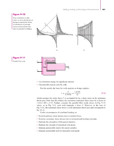
                       Figure 9–10                                 C

                       Stress distribution in fillet
                       welds: (a) stress distribution on
                       the legs as reported by Norris;                                 +
                       (b) distribution of principal   D                                         1
                       stresses and maximum shear
                       stress as reported by Salakian.                                           max
                                                                     +

                                                  +
                                                                                      0
                                               A                 −  B                  D                B

                                                                                                2


                                                                  (a)                         (b)


                       Figure 9–11
                       Parallel fillet welds.   F             l
                                                       h


                                                                              2F
                                               F


                                               • Use distortion energy for significant stresses.
                                               • Circumscribe typical cases by code.
                                                  For this model, the basis for weld analysis or design employs
                                                                              F      1.414F
                                                                        τ =        =                            (9–3)
                                                                            0.707hl    hl
                                               which assumes the entire force F is accounted for by a shear stress in the minimum
                                               throat area. Note that this inflates the maximum estimated shear stress by a factor of
                                               1.414/1.207 = 1.17. Further, consider the parallel fillet welds shown in Fig. 9–11
                                               where, as in Fig. 9–8, each weld transmits a force  F. However, in the case of
                                               Fig. 9–11, the maximum shear stress is at the minimum throat area and corresponds to
                                               Eq. (9–3).
                                                  Under circumstances of combined loading we
                                               • Examine primary shear stresses due to external forces.
                                               • Examine secondary shear stresses due to torsional and bending moments.
                                               • Estimate the strength(s) of the parent metal(s).
                                               • Estimate the strength of deposited weld metal.
                                               • Estimate permissible load(s) for parent metal(s).
                                               • Estimate permissible load for deposited weld metal.
   501   502   503   504   505   506   507   508   509   510   511