Page 503 - Shigley's Mechanical Engineering Design
P. 503

bud29281_ch09_475-516.qxd  12/16/2009  7:12 pm  Page 478 pinnacle 203:MHDQ196:bud29281:0073529281:bud29281_pagefiles:


                 478   Mechanical Engineering Design
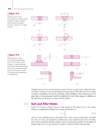
                  Figure 9–5                                                 60°

                  Butt or groove welds:
                  (a) square butt-welded on both
                  sides; (b) single V with 60°                                   2
                  bevel and root opening of
                  2 mm; (c) double V; (d) single                             2
                  bevel.                                                     60°
                                                  (a)                        (b)
                                                  60°                          45°


                                                  (c)                        (d)

                  Figure 9–6

                  Special groove welds:
                  (a) T joint for thick plates;
                  (b) U and J welds for thick
                  plates; (c) corner weld (may
                  also have a bead weld on inside
                  for greater strength but should      (a)                                 (b)
                  not be used for heavy loads);
                  (d) edge weld for sheet metal
                  and light loads.


                                                       (c)                                (d)


                                          residual stresses are not severe enough to cause concern; in some cases a light heat treat-
                                          ment after welding has been found helpful in relieving them. When the parts to be welded
                                          are thick, a preheating will also be of benefit. If the reliability of the component is to be
                                          quite high, a testing program should be established to learn what changes or additions to
                                          the operations are necessary to ensure the best quality.


                                  9–2     Butt and Fillet Welds
                                          Figure 9–7a shows a single V-groove weld loaded by the tensile force F. For either
                                          tension or compression loading, the average normal stress is
                                                                              F
                                                                         σ =                                (9–1)
                                                                              hl
                                          where h is the weld throat and l is the length of the weld, as shown in the figure. Note that
                                          the value of h does not include the reinforcement. The reinforcement can be desirable,
                                          but it varies somewhat and does produce stress concentration at point A in the figure. If
                                          fatigue loads exist, it is good practice to grind or machine off the reinforcement.
   498   499   500   501   502   503   504   505   506   507   508