Page 501 - Shigley's Mechanical Engineering Design
P. 501

bud29281_ch09_475-516.qxd  12/16/2009  7:12 pm  Page 476 pinnacle 203:MHDQ196:bud29281:0073529281:bud29281_pagefiles:


                 476   Mechanical Engineering Design
                                          Form can more readily pursue function with the help of joining processes such as weld-
                                          ing, brazing, soldering, cementing, and gluing—processes that are used extensively in
                                          manufacturing today. Whenever parts have to be assembled or fabricated, there is usu-
                                          ally good cause for considering one of these processes in preliminary design work.
                                          Particularly when sections to be joined are thin, one of these methods may lead to sig-
                                          nificant savings. The elimination of individual fasteners, with their holes and assembly
                                          costs, is an important factor. Also, some of the methods allow rapid machine assembly,
                                          furthering their attractiveness.
                                              Riveted permanent joints were common as the means of fastening rolled steel
                                          shapes to one another to form a permanent joint. The childhood fascination of seeing a
                                          cherry-red hot rivet thrown with tongs across a building skeleton to be unerringly
                                          caught by a person with a conical bucket, to be hammered pneumatically into its final
                                          shape, is all but gone.  Two developments relegated riveting to lesser prominence.
                                          The first was the development of high-strength steel bolts whose preload could be
                                          controlled. The second was the improvement of welding, competing both in cost and in
                                          latitude of possible form.
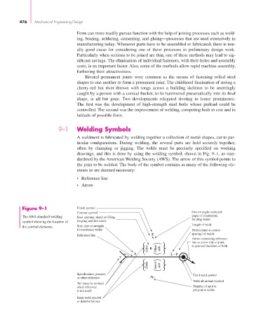

                                  9–1     Welding Symbols
                                          A weldment is fabricated by welding together a collection of metal shapes, cut to par-
                                          ticular configurations. During welding, the several parts are held securely together,
                                          often by clamping or jigging.  The welds must be precisely specified on working
                                          drawings, and this is done by using the welding symbol, shown in Fig. 9–1, as stan-
                                          dardized by the American Welding Society (AWS). The arrow of this symbol points to
                                          the joint to be welded. The body of the symbol contains as many of the following ele-
                                          ments as are deemed necessary:
                                          • Reference line
                                          • Arrow


                  Figure 9–1              Finish symbol
                                          Contour symbol                                    Groove angle; included
                  The AWS standard welding  Root opening; depth of filling                  angle of countersink
                                                                                            for plug welds
                  symbol showing the location of  for plug and slot welds
                                                                                            Length of weld
                  the symbol elements.    Size; size or strength
                                          for resistance welds                              Pitch (center-to-center
                                                                           F                spacing) of welds
                                          Reference line
                                                                           A
                                                                                            Arrow connecting reference
                                                                                            line to arrow side of joint,
                                                                                            to grooved member, or both
                                                                   S      R  Other  side  L – P
                                                             T           (Both            sides)  Arrow

                                          Specification; process;             side           Field weld symbol
                                          or other reference              (N)
                                                                                             Weld all around symbol
                                          Tail (may be omitted
                                          when reference                                     Number of spot or
                                          is not used)                                       projection welds
                                          Basic weld symbol
                                          or detail reference
   496   497   498   499   500   501   502   503   504   505   506