
Page 497 - Shigley's Mechanical Engineering Design
P. 497
bud29281_ch08_409-474.qxd 12/18/09 2:52 PM Page 472 epg Disk1:Desktop Folder:TEMPWORK:Don't-Delete Jobs:MHDQ196/Budynas:
472 Mechanical Engineering Design
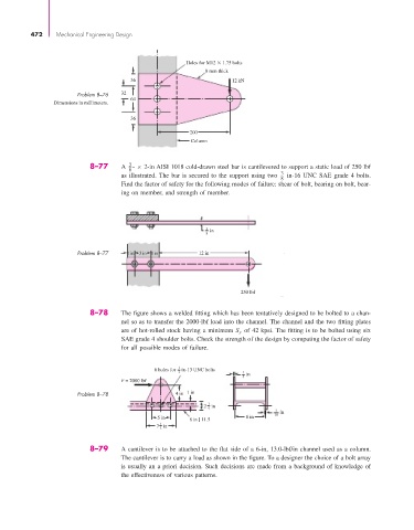
Holes for M12 1.75 bolts
8 mm thick
36 12 kN
Problem 8–76 32
64
Dimensions in millimeters.
36
200
Column
3
8–77 A - × 2-in AISI 1018 cold-drawn steel bar is cantilevered to support a static load of 250 lbf
8
as illustrated. The bar is secured to the support using two 3 in-16 UNC SAE grade 4 bolts.
8
Find the factor of safety for the following modes of failure: shear of bolt, bearing on bolt, bear-
ing on member, and strength of member.
3 in
8
Problem 8–77 1 in 3 in 1 in 12 in
250 lbf
8–78 The figure shows a welded fitting which has been tentatively designed to be bolted to a chan-
nel so as to transfer the 2000-lbf load into the channel. The channel and the two fitting plates
are of hot-rolled stock having a minimum S y of 42 kpsi. The fitting is to be bolted using six
SAE grade 4 shoulder bolts. Check the strength of the design by computing the factor of safety
for all possible modes of failure.
1
6 holes for in-13 UNC bolts
2 1 in
4
F = 2000 lbf
Problem 8–78 4 in 1 in
2 1 in
4
3 in
5 in 8 in 16
8 in [ 11.5
1
7in
2
8–79 A cantilever is to be attached to the flat side of a 6-in, 13.0-lbf/in channel used as a column.
The cantilever is to carry a load as shown in the figure. To a designer the choice of a bolt array
is usually an a priori decision. Such decisions are made from a background of knowledge of
the effectiveness of various patterns.