
Page 502 - Shigley's Mechanical Engineering Design
P. 502
bud29281_ch09_475-516.qxd 12/16/2009 7:12 pm Page 477 pinnacle 203:MHDQ196:bud29281:0073529281:bud29281_pagefiles:
Welding, Bonding, and the Design of Permanent Joints 477
• Basic weld symbols as in Fig. 9–2
• Dimensions and other data
• Supplementary symbols
• Finish symbols
• Tail
• Specification or process
The arrow side of a joint is the line, side, area, or near member to which the arrow
points. The side opposite the arrow side is the other side.
Figures 9–3 to 9–6 illustrate the types of welds used most frequently by designers.
For general machine elements most welds are fillet welds, though butt welds are used a
great deal in designing pressure vessels. Of course, the parts to be joined must be
arranged so that there is sufficient clearance for the welding operation. If unusual joints
are required because of insufficient clearance or because of the section shape, the
design may be a poor one and the designer should begin again and endeavor to synthe-
size another solution.
Since heat is used in the welding operation, there are metallurgical changes in the
parent metal in the vicinity of the weld. Also, residual stresses may be introduced because
of clamping or holding or, sometimes, because of the order of welding. Usually these
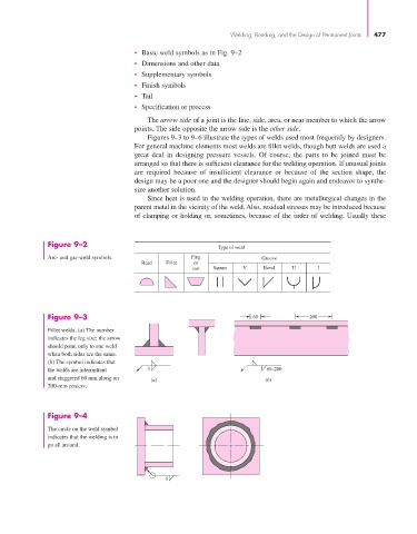
Figure 9–2
Type of weld
Arc- and gas-weld symbols. Plug Groove
Bead Fillet or
slot Square V Bevel U J
Figure 9–3 60 200
Fillet welds. (a) The number
indicates the leg size; the arrow
should point only to one weld
when both sides are the same.
(b) The symbol indicates that
the welds are intermittent 5 60–200
and staggered 60 mm along on (a) (b)
200-mm centers.
Figure 9–4
The circle on the weld symbol
indicates that the welding is to
go all around.
5