Page 505 - Shigley's Mechanical Engineering Design
P. 505
bud29281_ch09_475-516.qxd  12/16/2009  7:12 pm  Page 480 pinnacle 203:MHDQ196:bud29281:0073529281:bud29281_pagefiles:


                 480   Mechanical Engineering Design
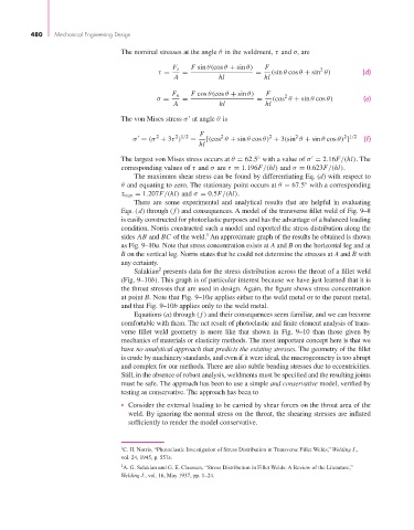
                                          The nominal stresses at the angle θ in the weldment, τ and σ, are


                                                        F s   F sin θ(cos θ + sin θ)  F           2
                                                    τ =    =                    =   (sin θ cos θ + sin θ)    (d)
                                                         A           hl           hl
                                                        F n   F cos θ(cos θ + sin θ)  F  2
                                                    σ =    =                    =   (cos θ + sin θ cos θ)     (e)
                                                         A           hl           hl
                                          The von Mises stress σ at angle θ is

                                                                                   2
                                                         2 1/2
                                                                                                        2 1/2
                                                    2
                                                                      2
                                                                                           2

                                             σ = (σ + 3τ )   =  F  [(cos θ + sin θ cos θ) + 3(sin θ + sin θ cos θ) ]  (f)
                                                                hl
                                          The largest von Mises stress occurs at θ = 62.5 with a value of σ = 2.16F/(hl). The
                                                                                ◦

                                          corresponding values of τ and σ are τ = 1.196F/(hl) and σ = 0.623F/(hl).
                                              The maximum shear stress can be found by differentiating Eq. (d) with respect to
                                          θ and equating to zero. The stationary point occurs at θ = 67.5 with a corresponding
                                                                                             ◦
                                          τ max = 1.207F/(hl) and σ = 0.5F/(hl).
                                              There are some experimental and analytical results that are helpful in evaluating
                                          Eqs. (d) through ( f ) and consequences. A model of the transverse fillet weld of Fig. 9–8
                                          is easily constructed for photoelastic purposes and has the advantage of a balanced loading
                                          condition. Norris constructed such a model and reported the stress distribution along the
                                                                  1
                                          sides AB and BC of the weld. An approximate graph of the results he obtained is shown
                                          as Fig. 9–10a. Note that stress concentration exists at A and B on the horizontal leg and at
                                          B on the vertical leg. Norris states that he could not determine the stresses at A and B with
                                          any certainty.
                                                    2
                                              Salakian presents data for the stress distribution across the throat of a fillet weld
                                          (Fig. 9–10b). This graph is of particular interest because we have just learned that it is
                                          the throat stresses that are used in design. Again, the figure shows stress concentration
                                          at point B. Note that Fig. 9–10a applies either to the weld metal or to the parent metal,
                                          and that Fig. 9–10b applies only to the weld metal.
                                              Equations (a) through ( f ) and their consequences seem familiar, and we can become
                                          comfortable with them. The net result of photoelastic and finite element analysis of trans-
                                          verse fillet weld geometry is more like that shown in Fig. 9–10 than those given by
                                          mechanics of materials or elasticity methods. The most important concept here is that we
                                          have no analytical approach that predicts the existing stresses. The geometry of the fillet
                                          is crude by machinery standards, and even if it were ideal, the macrogeometry is too abrupt
                                          and complex for our methods. There are also subtle bending stresses due to eccentricities.
                                          Still, in the absence of robust analysis, weldments must be specified and the resulting joints
                                          must be safe. The approach has been to use a simple and conservative model, verified by
                                          testing as conservative. The approach has been to

                                          • Consider the external loading to be carried by shear forces on the throat area of the
                                            weld. By ignoring the normal stress on the throat, the shearing stresses are inflated
                                            sufficiently to render the model conservative.


                                          1 C. H. Norris, “Photoelastic Investigation of Stress Distribution in Transverse Fillet Welds,” Welding J.,
                                          vol. 24, 1945, p. 557s.
                                          2 A. G. Salakian and G. E. Claussen, “Stress Distribution in Fillet Welds: A Review of the Literature,”
                                          Welding J., vol. 16, May 1937, pp. 1–24.

