
Page 509 - Shigley's Mechanical Engineering Design
P. 509
bud29281_ch09_475-516.qxd 12/16/2009 7:12 pm Page 484 pinnacle 203:MHDQ196:bud29281:0073529281:bud29281_pagefiles:
484 Mechanical Engineering Design
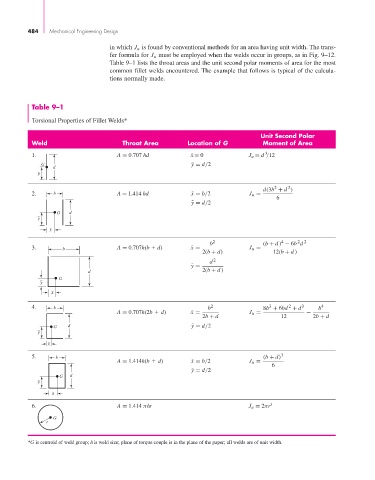
in which J u is found by conventional methods for an area having unit width. The trans-
fer formula for J u must be employed when the welds occur in groups, as in Fig. 9–12.
Table 9–1 lists the throat areas and the unit second polar moments of area for the most
common fillet welds encountered. The example that follows is typical of the calcula-
tions normally made.
Table 9–1
Torsional Properties of Fillet Welds*
Unit Second Polar
Weld Throat Area Location of G Moment of Area
3
1. A = 0.707 hd x ¯ = 0 J u = d /12
G ¯ y = d/2
d
y
2
2
d(3b + d )
2. b A = 1.414 hd ¯ x = b/2 J u = 6
¯ y = d/2
G d
y
x
2 2
4
b 2 (b + d ) − 6b d
3. b A = 0.707h(b d) ¯ x = J u =
2(b + d) 12(b + d )
d 2
¯ y =
d 2(b + d )
G
y
x
4. b b 2 8b + 6bd + d 3 b 4
3
2
A = 0.707h(2b d) ¯ x = J u = −
2b + d 12 2b + d
G d ¯ y = d/2
y
x
5. b (b + d) 3
A = 1.414h(b d) ¯ x = b/2 J u =
6
¯ y = d/2
G d
y
x
6. A = 1.414 πhr J u = 2πr 3
G
r
*G is centroid of weld group; h is weld size; plane of torque couple is in the plane of the paper; all welds are of unit width.