
Page 508 - Shigley's Mechanical Engineering Design
P. 508
bud29281_ch09_475-516.qxd 12/16/2009 7:12 pm Page 483 pinnacle 203:MHDQ196:bud29281:0073529281:bud29281_pagefiles:
Welding, Bonding, and the Design of Permanent Joints 483
Figure 9–13 y
x
2
b
2
G
2
t 2
1 G r 2 y 2
d r 1 y
O G 1 x
x 1 M
t
1
x
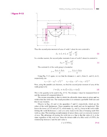
Thus the second polar moment of area of weld 1 about its own centroid is
t 1 d 3 dt 1 3
J G1 = I x + I y = + (b)
12 12
In a similar manner, the second polar moment of area of weld 2 about its centroid is
bt 2 3 t 2 b 3
J G2 = + (c)
12 12
The centroid G of the weld group is located at
A 1 x 1 + A 2 x 2 A 1 y 1 + A 2 y 2
¯ x = ¯ y =
A A
Using Fig. 9–13 again, we see that the distances r 1 and r 2 from G 1 and G 2 to G,
respectively, are
2
2 1/2
2
2 1/2
r 1 = [(¯ − x 1 ) +¯y ] r 2 = [(y 2 −¯y) + (x 2 −¯) ]
x
x
Now, using the parallel-axis theorem, we find the second polar moment of area of the
weld group to be
2 2
J = J G1 + A 1 r 1 + J G2 + A 2 r 2 (d)
This is the quantity to be used in Eq. (9–5). The distance r must be measured from G
and the moment M computed about G.
The reverse procedure is that in which the allowable shear stress is given and we
wish to find the weld size. The usual procedure is to estimate a probable weld size and
then to use iteration.
3
3
Observe in Eqs. (b) and (c) the quantities t and t , respectively, which are the
1
2
cubes of the weld thicknesses. These quantities are small and can be neglected. This
3
3
leaves the terms t 1 d /12 and t 2 b /12, which make J G1 and J G2 linear in the weld width.
Setting the weld thicknesses t 1 and t 2 to unity leads to the idea of treating each fillet
weld as a line. The resulting second moment of area is then a unit second polar moment
of area. The advantage of treating the weld size as a line is that the value of J u is the
same regardless of the weld size. Since the throat width of a fillet weld is 0.707h, the
relationship between J and the unit value is
(9–6)
J = 0.707hJ u