
Page 504 - Shigley's Mechanical Engineering Design
P. 504
bud29281_ch09_475-516.qxd 12/16/2009 7:12 pm Page 479 pinnacle 203:MHDQ196:bud29281:0073529281:bud29281_pagefiles:
Welding, Bonding, and the Design of Permanent Joints 479
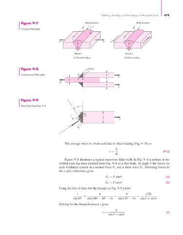
Figure 9–7 Reinforcement Reinforcement
A
A typical butt joint.
l l
F
F F F
Throat h Throat h
(a) Tensile loading (b) Shear loading
Figure 9–8 Throat
A transverse fillet weld. D C h
F
h A B
2F
h
F
Figure 9–9 x
Free body from Fig. 9–8.
t 45
h
F s F
F n
y
The average stress in a butt weld due to shear loading (Fig. 9–7b) is
F
τ = (9–2)
hl
Figure 9–8 illustrates a typical transverse fillet weld. In Fig. 9–9 a portion of the
welded joint has been isolated from Fig. 9–8 as a free body. At angle θ the forces on
each weldment consist of a normal force F n and a shear force F s . Summing forces in
the x and y directions gives
F s = F sin θ (a)
F n = F cos θ (b)
Using the law of sines for the triangle in Fig. 9–9 yields
√
t h h 2h
= = =
sin 45 ◦ sin(180 − 45 − θ) sin(135 − θ) cos θ + sin θ
◦
◦
◦
Solving for the throat thickness t gives
h
t = (c)
cos θ + sin θ