
Page 507 - Shigley's Mechanical Engineering Design
P. 507
bud29281_ch09_475-516.qxd 12/16/2009 7:12 pm Page 482 pinnacle 203:MHDQ196:bud29281:0073529281:bud29281_pagefiles:
482 Mechanical Engineering Design
9–3 Stresses in Welded Joints in Torsion
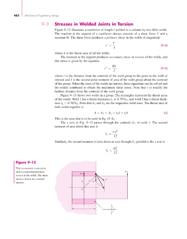
Figure 9–12 illustrates a cantilever of length l welded to a column by two fillet welds.
The reaction at the support of a cantilever always consists of a shear force V and a
moment M. The shear force produces a primary shear in the welds of magnitude
V
(9–4)
τ =
A
where A is the throat area of all the welds.
The moment at the support produces secondary shear or torsion of the welds, and
this stress is given by the equation
Mr
(9–5)
τ =
J
where r is the distance from the centroid of the weld group to the point in the weld of
interest and J is the second polar moment of area of the weld group about the centroid
of the group. When the sizes of the welds are known, these equations can be solved and
the results combined to obtain the maximum shear stress. Note that r is usually the
farthest distance from the centroid of the weld group.
Figure 9–13 shows two welds in a group. The rectangles represent the throat areas
of the welds. Weld 1 has a throat thickness t 1 = 0.707h 1 , and weld 2 has a throat thick-
ness t 2 = 0.707h 2 . Note that h 1 and h 2 are the respective weld sizes. The throat area of
both welds together is
A = A 1 + A 2 = t 1 d + t 2 b (a)
This is the area that is to be used in Eq. (9–4).
The x axis in Fig. 9–13 passes through the centroid G 1 of weld 1. The second
moment of area about this axis is
t 1 d 3
I x =
12
Similarly, the second moment of area about an axis through G 1 parallel to the y axis is
dt 1 3
I y =
12
Figure 9–12
This is a moment connection;
such a connection produces O′ F
torsion in the welds. The shear
stresses shown are resultant ′′
r ′
stresses. r o
O
l