Page 510 - Shigley's Mechanical Engineering Design
P. 510

bud29281_ch09_475-516.qxd  12/24/2009  1:46 pm  Page 485 pinnacle s-171:Desktop Folder:Temp Work:Don't Delete (Jobs):MHDQ196/Budynas:


                                                                         Welding, Bonding, and the Design of Permanent Joints  485


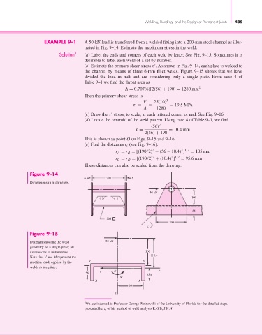
                             EXAMPLE 9–1       A 50-kN load is transferred from a welded fitting into a 200-mm steel channel as illus-
                                               trated in Fig. 9–14. Estimate the maximum stress in the weld.
                                    Solution 3  (a) Label the ends and corners of each weld by letter. See Fig. 9–15. Sometimes it is
                                               desirable to label each weld of a set by number.

                                               (b) Estimate the primary shear stress τ . As shown in Fig. 9–14, each plate is welded to
                                               the channel by means of three 6-mm fillet welds. Figure 9–15 shows that we have
                                               divided the load in half and are considering only a single plate. From case 4 of
                                               Table 9–1 we find the throat area as
                                                                 A = 0.707(6)[2(56) + 190] = 1280 mm 2
                                               Then the primary shear stress is
                                                                         V   25(10) 3

                                                                    τ =    =        = 19.5MPa
                                                                         A     1280
                                               (c) Draw the τ stress, to scale, at each lettered corner or end. See Fig. 9–16.

                                               (d) Locate the centroid of the weld pattern. Using case 4 of Table 9–1, we find
                                                                            (56) 2
                                                                      ¯ x =         = 10.4mm
                                                                         2(56) + 190
                                               This is shown as point O on Figs. 9–15 and 9–16.
                                               (e) Find the distances r i (see Fig. 9–16):
                                                                             2
                                                                                         2 1/2
                                                            r A = r B = [(190/2) + (56 − 10.4) ]  = 105 mm
                                                                                     2 1/2
                                                                             2
                                                            r C = r D = [(190/2) + (10.4) ]  = 95.6mm
                                               These distances can also be scaled from the drawing.
                       Figure 9–14
                                               6        200         6
                       Dimensions in millimeters.
                                                                            50 kN
                                                      6      6                                100


                                                                                              56
                                                        200
                                                                                    190
                                                                          6
                       Figure 9–15
                       Diagram showing the weld         25 kN
                       geometry on a single plate; all
                       dimensions in millimeters.                         100
                                                                            110.4
                       Note that V and M represent the
                       reaction loads applied by the  C                 D
                       welds to the plate.
                                                      V     O                   y
                                               56
                                                                          45.6
                                                              M
                                                    B                  A
                                                                  95
                                                            x

                                               3 We are indebted to Professor George Piotrowski of the University of Florida for the detailed steps,
                                               presented here, of his method of weld analysis R.G.B, J.K.N.
   505   506   507   508   509   510   511   512   513   514   515