Page 512 - Shigley's Mechanical Engineering Design
P. 512

bud29281_ch09_475-516.qxd  12/16/2009  7:12 pm  Page 487 pinnacle 203:MHDQ196:bud29281:0073529281:bud29281_pagefiles:


                                                                         Welding, Bonding, and the Design of Permanent Joints  487
                                       9–4     Stresses in Welded Joints in Bending

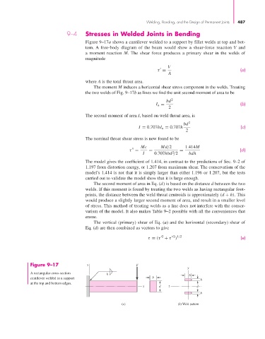
                                               Figure 9–17a shows a cantilever welded to a support by fillet welds at top and bot-
                                               tom. A free-body diagram of the beam would show a shear-force reaction  V and
                                               a moment reaction  M. The shear force produces a primary shear in the welds of
                                               magnitude

                                                                                   V
                                                                                                                  (a)
                                                                              τ =
                                                                                   A
                                               where A is the total throat area.
                                                  The moment M induces a horizontal shear stress component in the welds. Treating
                                               the two welds of Fig. 9–17b as lines we find the unit second moment of area to be

                                                                                  bd 2
                                                                              I u =                               (b)
                                                                                   2
                                               The second moment of area I, based on weld throat area, is
                                                                                          bd 2
                                                                      I = 0.707hI u = 0.707h                      (c)
                                                                                          2
                                               The nominal throat shear stress is now found to be
                                                                       Mc       Md/2      1.414M
                                                                                                                  (d)
                                                                  τ =     =             =
                                                                                     2
                                                                        I    0.707hbd /2    bdh
                                               The model gives the coefficient of 1.414, in contrast to the predictions of Sec. 9–2 of
                                               1.197 from distortion energy, or 1.207 from maximum shear. The conservatism of the
                                               model’s 1.414 is not that it is simply larger than either 1.196 or 1.207, but the tests
                                               carried out to validate the model show that it is large enough.
                                                  The second moment of area in Eq. (d) is based on the distance d between the two
                                               welds. If this moment is found by treating the two welds as having rectangular foot-
                                               prints, the distance between the weld throat centroids is approximately (d + h). This
                                               would produce a slightly larger second moment of area, and result in a smaller level
                                               of stress. This method of treating welds as a line does not interfere with the conser-
                                               vatism of the model. It also makes Table 9–2 possible with all the conveniences that
                                               ensue.
                                                  The vertical (primary) shear of Eq. (a) and the horizontal (secondary) shear of
                                               Eq. (d) are then combined as vectors to give

                                                                                 2    2 1/2
                                                                          τ = (τ + τ )                            (e)


                       Figure 9–17             y                     F
                                                                                           y
                       A rectangular cross-section      h                                   b
                       cantilever welded to a support                       b                    h
                       at the top and bottom edges.
                                                                        x      d   z           d
                                                                                                 h

                                                               (a)                     (b) Weld pattern
   507   508   509   510   511   512   513   514   515   516   517