
Page 496 - Shigley's Mechanical Engineering Design
P. 496
bud29281_ch08_409-474.qxd 12/16/2009 7:11 pm Page 471 pinnacle 203:MHDQ196:bud29281:0073529281:bud29281_pagefiles:
Screws, Fasteners, and the Design of Nonpermanent Joints 471
8–72 Standard design practice, as exhibited by the solutions to Probs. 8–66 to 8–70, is to assume
that the bolts, or rivets, share the shear equally. For many situations, such an assumption may
lead to an unsafe design. Consider the yoke bracket of Prob. 8–61, for example. Suppose this
bracket is bolted to a wide-flange column with the centerline through the two bolts in the ver-
tical direction. A vertical load through the yoke-pin hole at distance B from the column flange
would place a shear load on the bolts as well as a tensile load. The tensile load comes about
because the bracket tends to pry itself about the bottom corner, much like a claw hammer, exert-
ing a large tensile load on the upper bolt. In addition, it is almost certain that both the spac-
ing of the bolt holes and their diameters will be slightly different on the column flange from
what they are on the yoke bracket. Thus, unless yielding occurs, only one of the bolts will take
the shear load. The designer has no way of knowing which bolt this will be.
1
In this problem the bracket is 8 in long, A = 2 in, B = 3 in, C = 6 in, and the col-
1
umn flange is 1 2 in thick. The bolts are -in UNC SAE grade 4. The nuts are tightened to
2
75 percent of proof load. The vertical yoke-pin load is 2500 lbf. If the upper bolt takes all
the shear load as well as the tensile load, how closely does the bolt stress approach the
proof strength?
8–73 The bearing of Prob. 8–46 is bolted to a vertical surface and supports a horizontal shaft. The
bolts used have coarse threads and are M20 ISO 5.8. The joint constant is C = 0.25, and the
dimensions are A = 20 mm, B = 50 mm, and C = 160 mm. The bearing base is 240 mm long.
The bearing load is 14 kN. If the bolts are tightened to 75 percent of proof load, will the bolt
stress exceed the proof strength? Use worst-case loading, as discussed in Prob. 8–72.
8–74 A split-ring clamp-type shaft collar such as is described in Prob. 5–67 must resist an axial load
of 1000 lbf. Using a design factor of n = 3 and a coefficient of friction of 0.12, specify an SAE
Grade 5 cap screw using fine threads. What wrench torque should be used if a lubricated screw
is used?
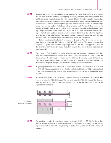
8–75 A vertical channel 152 × 76 (see Table A–7) has a cantilever beam bolted to it as shown. The
channel is hot-rolled AISI 1006 steel. The bar is of hot-rolled AISI 1015 steel. The shoulder
bolts are M10 × 1.5 ISO 5.8. For a design factor of 2.0, find the safe force F that can be
applied to the cantilever.
12
F
Problem 8–75
Dimensions in millimeters. 50
A O B
50 50 26 125
8–76 The cantilever bracket is bolted to a column with three M12 × 1.75 ISO 5.8 bolts. The
bracket is made from AISI 1020 hot-rolled steel. Find the factors of safety for the follow-
ing failure modes: shear of bolts, bearing of bolts, bearing of bracket, and bending of
bracket.