
Page 494 - Shigley's Mechanical Engineering Design
P. 494
bud29281_ch08_409-474.qxd 12/16/2009 7:11 pm Page 469 pinnacle 203:MHDQ196:bud29281:0073529281:bud29281_pagefiles:
Screws, Fasteners, and the Design of Nonpermanent Joints 469
w L w
t
D
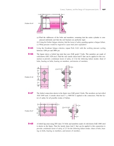
Problem 8–64
(a) Find the stiffnesses of the bolts and members, assuming that the entire cylinder is com-
pressed uniformly and that the end brackets are perfectly rigid.
(b) Using the Gerber fatigue criterion, find the factor of safety guarding against a fatigue failure.
(c) What pressure would be required to cause total joint separation?
8–65 Using the Goodman fatigue criterion, repeat Prob. 8–64 with the working pressure cycling
between 1200 psi and 2000 psi.
8–66 The figure shows a bolted lap joint that uses SAE grade 5 bolts. The members are made of
cold-drawn AISI 1020 steel. Find the safe tensile shear load F that can be applied to this con-
nection to provide a minimum factor of safety of 2 for the following failure modes: shear of
bolts, bearing on bolts, bearing on members, and tension of members.
5 in
16
1 in-20 UNC
4
5 in
8
Problem 8–66 1 1 8 in
5 in
8
1
1 in
1 in 4
4
8–67 The bolted connection shown in the figure uses SAE grade 8 bolts. The members are hot-rolled
AISI 1040 steel. A tensile shear load F = 5000 lbf is applied to the connection. Find the fac-
tor of safety for all possible modes of failure.
5 in 1 in 5 in
8 1 8 8 1 in
4
5 in-18 UNC
5 in 16
8
Problem 8–67
5 in
8
1 in
4
8–68 A bolted lap joint using ISO class 5.8 bolts and members made of cold-drawn SAE 1040 steel
is shown in the figure. Find the tensile shear load F that can be applied to this connection to
provide a minimum factor of safety of 2.5 for the following failure modes: shear of bolts, bear-
ing on bolts, bearing on members, and tension of members.