
Page 490 - Shigley's Mechanical Engineering Design
P. 490
bud29281_ch08_409-474.qxd 12/16/2009 7:11 pm Page 465 pinnacle 203:MHDQ196:bud29281:0073529281:bud29281_pagefiles:
Screws, Fasteners, and the Design of Nonpermanent Joints 465
• Obtain a joint stiffness constant C between 0.2 and 0.3 to ensure most of the pressure
load is carried by the members.
• The bolts may be reused, so the yielding factor of safety should be at least 1.1.
• The overload factor and the joint separation factor should allow for the pressure to exceed
the expected pressure by 15 percent.
Originating
Problem Problem
Number Number
8–41 8–33
8–42 8–34
8–43 8–35
8–44 8–36
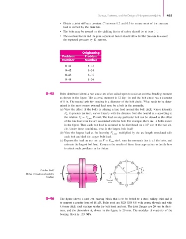
8–45 Bolts distributed about a bolt circle are often called upon to resist an external bending moment
as shown in the figure. The external moment is 12 kip · in and the bolt circle has a diameter
of 8 in. The neutral axis for bending is a diameter of the bolt circle. What needs to be deter-
mined is the most severe external load seen by a bolt in the assembly.
(a) View the effect of the bolts as placing a line load around the bolt circle whose intensity
F , in pounds per inch, varies linearly with the distance from the neutral axis according to
b
the relation F = F b,max R sin θ. The load on any particular bolt can be viewed as the effect
b
of the line load over the arc associated with the bolt. For example, there are 12 bolts shown
in the figure. Thus each bolt load is assumed to be distributed on a 30° arc of the bolt cir-
cle. Under these conditions, what is the largest bolt load?
(b) View the largest load as the intensity F b,max multiplied by the arc length associated with
each bolt and find the largest bolt load.
(c) Express the load on any bolt as F = F max sin θ, sum the moments due to all the bolts, and
estimate the largest bolt load. Compare the results of these three approaches to decide how
to attack such problems in the future.
R
Problem 8–45
Bolted connection subjected to M M
bending.
Neutral
axis
8–46 The figure shows a cast-iron bearing block that is to be bolted to a steel ceiling joist and is
to support a gravity load of 18 kN. Bolts used are M24 ISO 8.8 with coarse threads and with
4.6-mm-thick steel washers under the bolt head and nut. The joist flanges are 20 mm in thick-
ness, and the dimension A, shown in the figure, is 20 mm. The modulus of elasticity of the
bearing block is 135 GPa.