
Page 489 - Shigley's Mechanical Engineering Design
P. 489
bud29281_ch08_409-474.qxd 12/16/2009 7:11 pm Page 464 pinnacle 203:MHDQ196:bud29281:0073529281:bud29281_pagefiles:
464 Mechanical Engineering Design
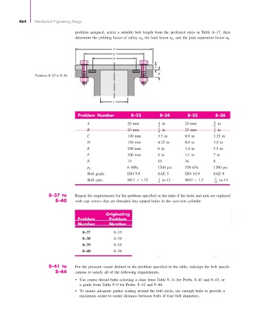
problem assigned, select a suitable bolt length from the preferred sizes in Table A–17, then
determine the yielding factor of safety n p, the load factor n L, and the joint separation factor n 0.
F
E
D
A
B
Problems 8–33 to 8–36
C
Problem Number 8–33 8–34 8–35 8–36
A 20 mm 1 in 20 mm 3 in
2 8
B 20 mm 5 in 25 mm 1 in
8 2
C 100 mm 3.5 in 0.8 m 3.25 in
D 150 mm 4.25 in 0.9 m 3.5 in
E 200 mm 6 in 1.0 m 5.5 in
F 300 mm 8 in 1.1 m 7 in
N 10 10 36 8
p g 6 MPa 1500 psi 550 kPa 1200 psi
Bolt grade ISO 9.8 SAE 5 ISO 10.9 SAE 8
Bolt spec. M12 × 1.75 1 in-13 M10 × 1.5 7 in-14
2 16
8–37 to Repeat the requirements for the problem specified in the table if the bolts and nuts are replaced
8–40 with cap screws that are threaded into tapped holes in the cast-iron cylinder.
Originating
Problem Problem
Number Number
8–37 8–33
8–38 8–34
8–39 8–35
8–40 8–36
8–41 to For the pressure vessel defined in the problem specified in the table, redesign the bolt specifi-
8–44 cations to satisfy all of the following requirements.
• Use coarse-thread bolts selecting a class from Table 8–11 for Probs. 8–41 and 8–43, or
a grade from Table 8–9 for Probs. 8–42 and 8–44.
• To ensure adequate gasket sealing around the bolt circle, use enough bolts to provide a
maximum center-to-center distance between bolts of four bolt diameters.