
Page 85 - Shigley's Mechanical Engineering Design
P. 85
bud29281_ch02_031-070.qxd 11/11/09 09:34 PM Page 60 Debd Hard Disk1:Desktop Folder:Temp Work:Satya 10/11/09:
60 Mechanical Engineering Design
2–20 Composite Materials 14
Composite materials are formed from two or more dissimilar materials, each of which
contributes to the final properties. Unlike metallic alloys, the materials in a composite
remain distinct from each other at the macroscopic level.
Most engineering composites consist of two materials: a reinforcement called a
filler and a matrix. The filler provides stiffness and strength; the matrix holds the mate-
rial together and serves to transfer load among the discontinuous reinforcements. The
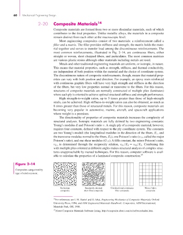
most common reinforcements, illustrated in Fig. 2–14, are continuous fibers, either
straight or woven, short chopped fibers, and particulates. The most common matrices
are various plastic resins although other materials including metals are used.
Metals and other traditional engineering materials are uniform, or isotropic, in nature.
This means that material properties, such as strength, stiffness, and thermal conductivity,
are independent of both position within the material and the choice of coordinate system.
The discontinuous nature of composite reinforcements, though, means that material prop-
erties can vary with both position and direction. For example, an epoxy resin reinforced
with continuous graphite fibers will have very high strength and stiffness in the direction
of the fibers, but very low properties normal or transverse to the fibers. For this reason,
structures of composite materials are normally constructed of multiple plies (laminates)
where each ply is oriented to achieve optimal structural stiffness and strength performance.
High strength-to-weight ratios, up to 5 times greater than those of high-strength
steels, can be achieved. High stiffness-to-weight ratios can also be obtained, as much as
8 times greater than those of structural metals. For this reason, composite materials are
becoming very popular in automotive, marine, aircraft, and spacecraft applications
where weight is a premium.
The directionality of properties of composite materials increases the complexity of
structural analyses. Isotropic materials are fully defined by two engineering constants:
Young’s modulus E and Poisson’s ratio ν. A single ply of a composite material, however,
requires four constants, defined with respect to the ply coordinate system. The constants
are two Young’s moduli (the longitudinal modulus in the direction of the fibers, E 1 , and
the transverse modulus normal to the fibers, E 2 ), one Poisson’s ratio (ν 12 , called the major
Poisson’s ratio), and one shear modulus (G 12 ). A fifth constant, the minor Poisson’s ratio,
ν 21 , is determined through the reciprocity relation, ν 21 /E 2 = ν 12 /E 1 . Combining this
with multiple plies oriented at different angles makes structural analysis of complex struc-
tures unapproachable by manual techniques. For this reason, computer software is avail-
able to calculate the properties of a laminated composite construction. 15
Figure 2–14
Composites categorized by
type of reinforcement.
Particulate Randomly oriented Unidirectional continuous Woven fabric
composite short fiber composite fiber composite composite
14 For references see I. M. Daniel and O. Ishai, Engineering Mechanics of Composite Materials, Oxford
University Press, 1994, and ASM Engineered Materials Handbook: Composites, ASM International,
Materials Park, OH, 1988.
15 About Composite Materials Software listing, http://composite.about.com/cs/software/index.htm.