
Page 408 - Standard Handbook Petroleum Natural Gas Engineering VOLUME2
P. 408
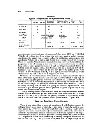
374   Production

                                                 Table 6-2
                                -.
                               Tmical Comnosltions of  Hydrocarbons Fluids Dl
                                                 Retrograde   Volatile Oil  or   Black   Aeay
                                   Dry Gas   Wet Gas   Condensate   Near  Critical  Oils  011   Oil
                     c,  (mle C)      90          70           55              30
                     c,-c, (lm31.  8)   9         22           30              35
                     G+ (=le%)         1           8           t5              35
                     GOR[ft'/abl]   m      150000  3000-150000   2000-3000    < 2000
                                                 (10000+)*    (3000-6000)*
                       I2NJ        m      > 27000  540-27000   360-540        c 360
                     API Llquid
                     Gravity                      40-60        45-70
                     Llquid  Specific
                     RaViV                       0.83-0.76     0.8-0.7


                    see retrograde behavior at reservoir pressures below about 2,500 psi (17.2 MPa).
                    Volatile oil  systems are  those  within  the  two-phase region  under  reservoir
                    conditions,  the  vapor  phase  corresponding to  condensate compositions and
                    conditions. Volatile oil is not an apt description because virtually all reservoir
                    fluids are volatile. What is  really meant is that the reservoir fluid exhibits the
                    properties of  an oil existing in the reservoir at a temperature near its critical
                    temperature. These properties include a high shrinkage immediately below the
                    bubble point.  In  extreme cases, this shrinkage can be as much as 45% of  the
                    hydrocarbon pore space within  10 psi (0.7 bar) below  the bubble point. Near-
                    critical oils have formation factor Bo of  2 or higher; the compositions are usually
                    characterized by  12.5  to 20 mole % heptanes or more.
                      Ordinary oils are characterized by GOR from 0 to approximately 200 ft3/bbl
                    (360 m3/m3) and Bo less than 2. Oils with high viscosity (about 10 cp), high oil
                    density and negligible gas/oil  ratio are called heavy oils. At surface conditions
                    may form tar sands. Oils with smaller than 10 cp viscosity are known as a black
                    oil or a dissolved gas oil system; no anomalies are in phase behavior. There is
                    no  sharp dividing line between  each  group  of  reservoir hydrocarbon fluid;
                    however,  liquid volume  percent versus pressure  diagram (Figure 6-5)  is  very
                    useful to understand the subject.
                      The significant point to be made is that when an oil system exists in intimate
                    contact with an associated gas cap, the bubble point pressure of the oil will be
                    equal to the dew point pressure of  the gas cap and both of  those values will be
                    equal to the static reservoir pressure at the gas-oil  contact (Figure 6-6).

                                     Reservolr Condltions Phase Behavlor
                      There is one phase flow in reservoir conditions if  well  flowing pressure Pwf
                    is higher than bubble point pressure P, or dew point pressure Pb and two-phase
                    flow occurs by  a wellbore. Reservoir depletion and production consist of  two
                    separate processes: flash liberation (vaporization) and differential liberation. A
                    schematic representation of  flash vaporization is  shown in Figure 6-7. At  stage 1
                    reservoir f hid is under  reservoir pressure and temperature at known volumes
                    V,. The pressure in the cell is covered by increasing the space available in the
                    cell  for  the  fluid  V,.   This  procedure is  repeated until  a large change in  the