
Page 110 - Steam Turbines Design, Applications, and Rerating
P. 110
Rotors for Impulse Turbines 91
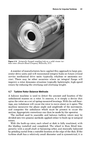
Figure 4.10 Integrally flanged coupling hub on a solid steam tur-
bine rotor. (Dresser-Rand Company, Wellsville, N.Y.)
A number of manufacturers have applied this approach to large gen-
erator drive units and will recommend integral hubs on future critical
service mechanical drive units (typically, ethylene or ammonia ser-
vice). There may be other occasions where an integral flange will
improve a rotor dynamics situation (typically lightweight, high-speed
rotors) by reducing the overhang and overhung weight.
4.7 Turbine Rotor Balance Methods
A balance machine is used to detect the amount and location of the
unbalanced masses on a rotor. In essence, it is simply a device that
spins the rotor on a set of spring-mounted bearings. With the soft bear-
ings, any imbalance will cause the rotor to move about as it spins. The
machine measures the phase angle and amplitude of the movement,
and computes the unbalance which must be present to cause the
motion. Appropriate corrections can then be made by the operator.
The method used to assemble and balance turbine rotors may be
divided into two general methods applied either to built-up or integral
rotors.
With the built-up rotor, each wheel or disk is fully machined, with
the blading installed and completed. The wheel is then fitted tem-
porarily with a small shaft or balancing arbor, and statically balanced
by grinding metal from a suitable location at the edge of the disk. If the
turbine shaft has a relatively small diameter and is symmetrical, it is