
Page 105 - Steam Turbines Design, Applications, and Rerating
P. 105
86 Chapter Four
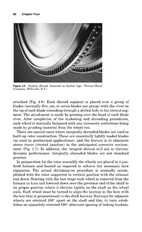
Figure 4.6 Bucket shroud fastened to bucket tips. (Dresser-Rand
Company, Wellsville, N.Y.)
attached (Fig. 4.6). Each shroud segment is placed over a group of
blades (normally five, six, or seven blades per group) with the rivet on
the tip of each blade extending through a drilled hole in the shroud seg-
ment. The attachment is made by peening over the head of each blade
rivet. After completion of the bucketing and shrouding procedures,
each wheel is statically balanced with any necessary corrections being
made by grinding material from the wheel rim.
There are special cases where integrally shrouded blades are used in
built-up rotor construction. These are essentially lightly loaded blades
(as used in geothermal applications), and the feature is to eliminate
stress risers (riveted junction) in the anticipated corrosive environ-
ment (Fig. 4.7). In addition, the integral shroud will aid in thermo-
dynamic performance. Integrally shrouded blades are not standard
practice.
In preparation for the rotor assembly the wheels are placed in a gas-
fired furnace and heated as required to achieve the necessary bore
expansion. The actual shrinking-on procedure is normally accom-
plished with the rotor supported in vertical position with the exhaust
end down. Starting with the last stage each wheel is removed from the
furnace in turn and lowered down over the governor end of the shaft to
its proper position where it shrinks tightly on the shaft as the wheel
cools. Each wheel must be turned to align the keyway in the bore with
the key that is prepositioned in the shaft keyway. Keyways for adjacent
wheels are oriented 180° apart on the shaft and this, in turn, estab-
lishes an oppositely oriented 180° alternate spacing of locking buckets.