
Page 104 - Steam Turbines Design, Applications, and Rerating
P. 104
Rotors for Impulse Turbines 85
Figure 4.4 Wheel groove machin-
ing and inspection details are
important to ensure turbine reli-
ability. (Dresser-Rand Company,
Wellsville, N.Y.)
root to dovetail groove. Once in the groove each bucket may be driven
around to its ultimate position in the wheel. Buckets are, thereby,
stacked in both directions from a point 180° opposite the access open-
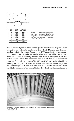
ing. The final bucket to be put in the wheel is a special locking bucket.
This bucket has a specially formed root that is designed to fill the
radial access slot in the wheel rim and lock all the other buckets in
position. This locking bucket (Fig. 4.5) itself is held in the wheel by a
locking pin (or pins) fitted into a drilled and reamed hole that passes
axially through the blade root and both sides of the wheel rim. After
the blades are completely assembled in the wheel, the bucket shroud is
Figure 4.5 Steam turbine locking bucket. (Dresser-Rand Company,
Wellsville, N.Y.)